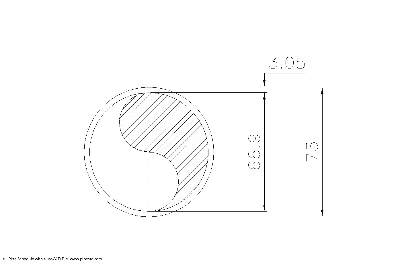
Schedule 10 pipe 2 1/2 inch (DN65) is a useful reference for engineers, drafters, estimators, fabricators, and purchasing teams working with steel piping. Use the dimension table on this page to check the pipe’s outside diameter, wall thickness, inside diameter, and published weight before preparing layouts, material takeoffs, or fabrication documentation.
For related sizing work, compare this page with the site’s pipe schedule reference, NPS and DN guide, and steel pipe dimensions resources. The downloadable DWG can also support preliminary CAD layout and drafting tasks, subject to project-specific verification.
Schedule 10 pipe 2 1/2 inch (DN65) is a standard steel pipe size commonly used in piping design, fabrication, drafting, and estimation work. This page provides the standard dimensions, wall thickness, inside diameter, and weight per meter for NPS 2 1/2 Schedule 10 pipe based on ASME B36.10.
2 1/2 Inch Schedule 10 Pipe Dimensions
- Nominal Pipe Size (NPS): 2 1/2 inch
- Diameter Nominal (DN): DN65
- Outside Diameter (OD): 73 mm
- Wall Thickness: 3.05 mm
- Inside Diameter (ID): 66.9 mm
- Pipe Weight: 5.26 kg/m
- Pipe Weight Filled With Water: 8.77 kg/m
- Reference Standard: ASME B36.10
Schedule 10 Pipe 2 1/2 Inch Data Table
| Pipe Size | DN | OD (mm) | Wall Thickness (mm) | ID (mm) | Weight (kg/m) |
|---|---|---|---|---|---|
| 2 1/2 inch | 65 | 73 | 3.05 | 66.9 | 5.26 |
What Does Schedule 10 Mean?
Schedule 10 refers to the wall thickness series of the pipe. For the same nominal pipe size, the outside diameter remains fixed while the wall thickness changes depending on the schedule. A thicker wall generally increases pipe weight and reduces the inside diameter.
Typical Uses of 2 1/2 Inch Schedule 10 Pipe
NPS 2 1/2 Schedule 10 pipe is commonly used in utility systems, water transfer lines, low-pressure process piping, drainage applications, and general fabrication work where a lighter wall thickness is suitable. It is also a practical reference size for material takeoff, support planning, and piping layout.
Why Pipe Weight Matters
Pipe weight per meter is important for transport planning, support design, structural loading, fabrication estimates, and lifting calculations. Even in smaller piping systems, installed weight can affect support spacing, handling methods, and project cost.
2 1/2 Inch Schedule 10 Pipe Calculation Notes
The listed weight is based on standard steel pipe dimension data using the outside diameter and wall thickness of the pipe. Actual product weight may vary slightly depending on manufacturing tolerance, material grade, and supplier standard.
Frequently Asked Questions
What is the outside diameter of 2 1/2 inch Schedule 10 pipe?
The outside diameter is 73 mm.
What is the wall thickness of DN65 Schedule 10 pipe?
The wall thickness is 3.05 mm.
What is the inside diameter of NPS 2 1/2 Schedule 10 pipe?
The inside diameter is 66.9 mm.
How much does 2 1/2 inch Schedule 10 pipe weigh?
The approximate weight is 5.26 kg/m.
Which standard covers this pipe size?
This dimension data is based on ASME B36.10 for welded and seamless wrought steel pipe.
Conclusion
Schedule 10 pipe 2 1/2 inch (DN65) has an outside diameter of 73 mm, wall thickness of 3.05 mm, inside diameter of 66.9 mm, and a weight of 5.26 kg/m. It is a useful reference for piping design, drafting, estimating, and fabrication work.
How to Use This Pipe Dimension Reference
The nominal size identifies the pipe designation used in piping documents; it should not be treated as a direct measurement of the bore. For physical fit-up, clearance checks, and preliminary hydraulic work, use the listed outside diameter, wall thickness, and inside diameter rather than relying on the nominal designation alone.
Schedule describes a wall-thickness series. When comparing pipe schedules within the same nominal size, the outside diameter is generally retained while the wall thickness and resulting inside diameter change. That distinction is important when checking valve connections, fittings, supports, insulation clearances, and available flow area.
Design and Drafting Checks
- Use the outside diameter when coordinating clamps, supports, sleeves, insulation, and connection geometry.
- Use the wall thickness when reviewing fabrication details, weld preparation, corrosion allowances, and component interfaces.
- Use the inside diameter for preliminary bore and flow-area checks, then confirm the result with the governing design basis.
- Use the published pipe weight for estimating and support-load planning, while recognizing that delivered weight can vary with product tolerances and material details.
- Confirm the material specification, pressure-temperature requirements, corrosion basis, joining method, and applicable project codes before procurement or final design approval.
The accompanying DWG is most useful as a drafting reference. Check units, layer standards, connection details, and project drawing conventions before incorporating it into a controlled design package. For broader coordination, link this page to related references for pipe fittings, flange dimensions, pipe support design, and material takeoff methods.
Additional Questions About 2 1/2 Inch Schedule 10 Pipe
Are NPS 2 1/2 and DN65 interchangeable labels?
They are commonly used as corresponding nominal designations for this pipe size, but neither label should replace the dimensional data when checking a physical connection or clearance.
Can the listed weight be used for final support design?
It can support preliminary estimating and planning, but final support design should account for the complete installed condition, including contents, insulation, fittings, valves, supports, and applicable design loads.
Does Schedule 10 alone define pressure capability?
No. Pressure capability depends on more than the schedule designation. Material specification, manufacturing method, temperature, corrosion allowance, joining details, code requirements, and design conditions must also be reviewed.
What should be checked before using the DWG file?
Verify drawing units, geometry, file compatibility, layer conventions, dimensional accuracy, and project-specific connection requirements before using the file for issued design or fabrication documents.