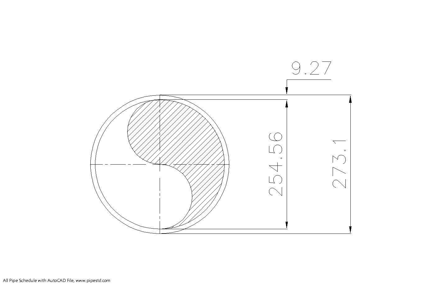
This reference page is intended for engineers, designers, drafters, fabricators, estimators, and procurement teams checking 10 inch Schedule 40 pipe data. It brings the NPS designation, DN designation, dimensional values, and weight information together so the same reference can support layout, material takeoff, fabrication, and early coordination work.
Use the dimensional table for identification and drawing coordination, then confirm project specifications, material requirements, connection details, and governing design conditions before releasing drawings or purchasing material. For related work, connect this page with the site’s references for pipe schedules, NPS and DN terminology, pipe fittings, flanges, and CAD or DWG resources.
Schedule 40 pipe 10 inch (DN250) is a standard steel pipe size commonly used in piping design, fabrication, drafting, and engineering estimation work. This page provides the standard dimensions and weight data for NPS 10 Schedule 40 pipe based on ANSI / ASME B36.10, including outside diameter, inside diameter, wall thickness, and weight per meter.
This size is widely used in industrial piping systems, utility services, water lines, and fabrication projects where accurate dimensional data is important for layout, support design, material takeoff, and installation planning.
10 Inch Schedule 40 Pipe Dimensions
- Nominal Pipe Size (NPS): 10 inch
- Diameter Nominal (DN): DN250
- Pipe Schedule: Schedule 40
- Outside Diameter (OD): 273.1 mm
- Wall Thickness: 9.27 mm
- Inside Diameter (ID): 254.46 mm
- Pipe Weight: 60.29 kg/m
- Pipe Weight Including Water: 111.11 kg/m
- Reference Standard: ANSI / ASME B36.10
Schedule 40 Pipe 10 Inch (DN250) Data Table
| NPS | DN | OD (mm) | Wall Thickness (mm) | ID (mm) | Weight (kg/m) |
|---|---|---|---|---|---|
| 10 inch | DN250 | 273.1 | 9.27 | 254.46 | 60.29 |
What Is 10 Inch Schedule 40 Pipe Used For?
10 inch Schedule 40 pipe is commonly used in industrial and utility piping systems where a standardized steel pipe size is required. Engineers, designers, and fabricators often use this size in:
- Water transmission and distribution systems
- Cooling water piping
- Industrial utility lines
- Process piping systems
- Plant layout and pipe routing work
- Fabrication and spool drawing preparation
Because this is a widely used pipe size, accurate dimensions and weight data are important for support design, transport planning, lifting studies, and material estimation.
Why These Dimensions Matter in Engineering
In piping and mechanical design, standard pipe dimensions are important for more than simple identification. The outside diameter is used for supports, clamps, insulation sizing, and equipment connection layouts. The inside diameter affects internal flow area and hydraulic calculations. The wall thickness is important for fabrication, welding preparation, and pipe strength, while the pipe weight per meter is essential for support load calculations and installation planning.
Using the correct DN250 Schedule 40 pipe dimensions helps reduce drafting errors, procurement mistakes, and field fit-up problems during construction and fabrication work.
10 Inch DN250 Schedule 40 Pipe for CAD and Drafting Work
For CAD, BIM, and piping drafting work, this size is commonly listed as NPS 10 or DN250. The standard OD of 273.1 mm is especially useful for routing clearance, support detailing, and nozzle or equipment connection references in both 2D drawings and 3D models.
This page can be used as a quick reference for 10 inch Schedule 40 pipe dimensions, DN250 pipe dimensions, and Schedule 40 steel pipe weight per meter during design, drafting, and estimation work.
Frequently Asked Questions
What is the outside diameter of 10 inch Schedule 40 pipe?
The outside diameter of 10 inch Schedule 40 pipe is 273.1 mm.
What is the wall thickness of DN250 Schedule 40 pipe?
The wall thickness is 9.27 mm.
What is the inside diameter of Schedule 40 pipe 10 inch?
The inside diameter is 254.46 mm.
How much does 10 inch Schedule 40 pipe weigh?
The pipe weight is 60.29 kg/m. The weight including water is 111.11 kg/m.
Which standard covers these dimensions?
These dimensions are based on ANSI / ASME B36.10.
Conclusion
Schedule 40 pipe 10 inch (DN250) is an important reference size for industrial piping, drafting, fabrication, and engineering calculations. With an OD of 273.1 mm, ID of 254.46 mm, wall thickness of 9.27 mm, and weight of 60.29 kg/m, it is a useful standard pipe size for engineers, designers, and estimators working with steel piping systems.
For more pipe schedule data, compare this size with nearby standard sizes such as 8 inch and 12 inch Schedule 40 pipe pages.
How to Read This Pipe Reference
NPS 10 and DN250 are two designation systems for the same nominal pipe size. The nominal designation is used for identification, while the listed outside diameter, wall thickness, and inside diameter are the practical values used when coordinating geometry. This distinction matters when a drawing or specification uses nominal size but a clearance, support, or connection detail depends on the actual pipe surface.
Using the Dimensions in Design and Drafting
Use the outside diameter when checking pipe routing, support and clamp interfaces, insulation space, and equipment or nozzle coordination. Use the inside diameter when a calculation requires the internal passage. Wall thickness supports fabrication review and dimensional checks, while the listed mass per meter can be carried into preliminary material takeoffs and support-load coordination.
The water-inclusive weight shown in the source table should be treated as a reference value for the stated basis. Actual operating and support conditions may also require consideration of the conveyed fluid, insulation, valves, fittings, lining, corrosion allowance, test condition, and other attached items. Final support and structural decisions require the applicable project design basis and engineering review.
Coordination With Fittings, Flanges, and CAD Files
A pipe size cannot be coordinated in isolation. Fittings, flanges, valves, gaskets, branches, and equipment connections must be checked against the project specification and the applicable dimensional references. In CAD or BIM work, use the listed pipe geometry as the pipe object basis, and verify that connected components, clearances, weld details, and support locations use compatible data.
Useful related internal references include the pipe schedule chart, NPS-to-DN conversion guide, pipe fitting dimensions, flange dimensions, and pipe support design guidance. The available DWG download can also be linked from this section as a drafting resource, with its use checked against the project’s layer, unit, and modeling conventions.
Practical Checks Before Using the Data
- Confirm that the drawing or specification calls for NPS 10, DN250, and Schedule 40.
- Check whether the project uses a compatible pipe, fitting, flange, and valve dimensional basis.
- Use the outside diameter for physical coordination rather than treating the nominal size as the modeled diameter.
- Confirm the applicable material, manufacturing, joining, corrosion, insulation, and testing requirements.
- Recheck loads and clearances when the line includes fluid, insulation, fittings, supports, or connected equipment.
Additional Reference Questions
Is nominal pipe size the same as the measured pipe diameter?
No. NPS and DN are identification designations. The actual outside diameter and other dimensions should be taken from the applicable dimensional reference, such as the values listed on this page.
Can this page replace a project piping specification?
No. It is a dimensional and weight reference. Project specifications still control material, manufacturing, end preparation, joining, testing, corrosion protection, and service requirements.
Should fittings and flanges use the same schedule designation?
Not automatically. Connected components must be selected and checked against the relevant component standard and the project piping class. Confirm bore, connection, rating, facing, and dimensional compatibility before fabrication.
How should the DWG resource be used?
Use the DWG as a drafting aid for the referenced pipe size, then verify units, layers, insertion behavior, geometry, and project standards before incorporating it into production drawings or models.
Why should support loads be reviewed separately?
Pipe weight is only one part of a support condition. Fluid, insulation, fittings, valves, test conditions, thermal effects, and connected equipment can change the governing load case, so support design requires project-specific engineering review.