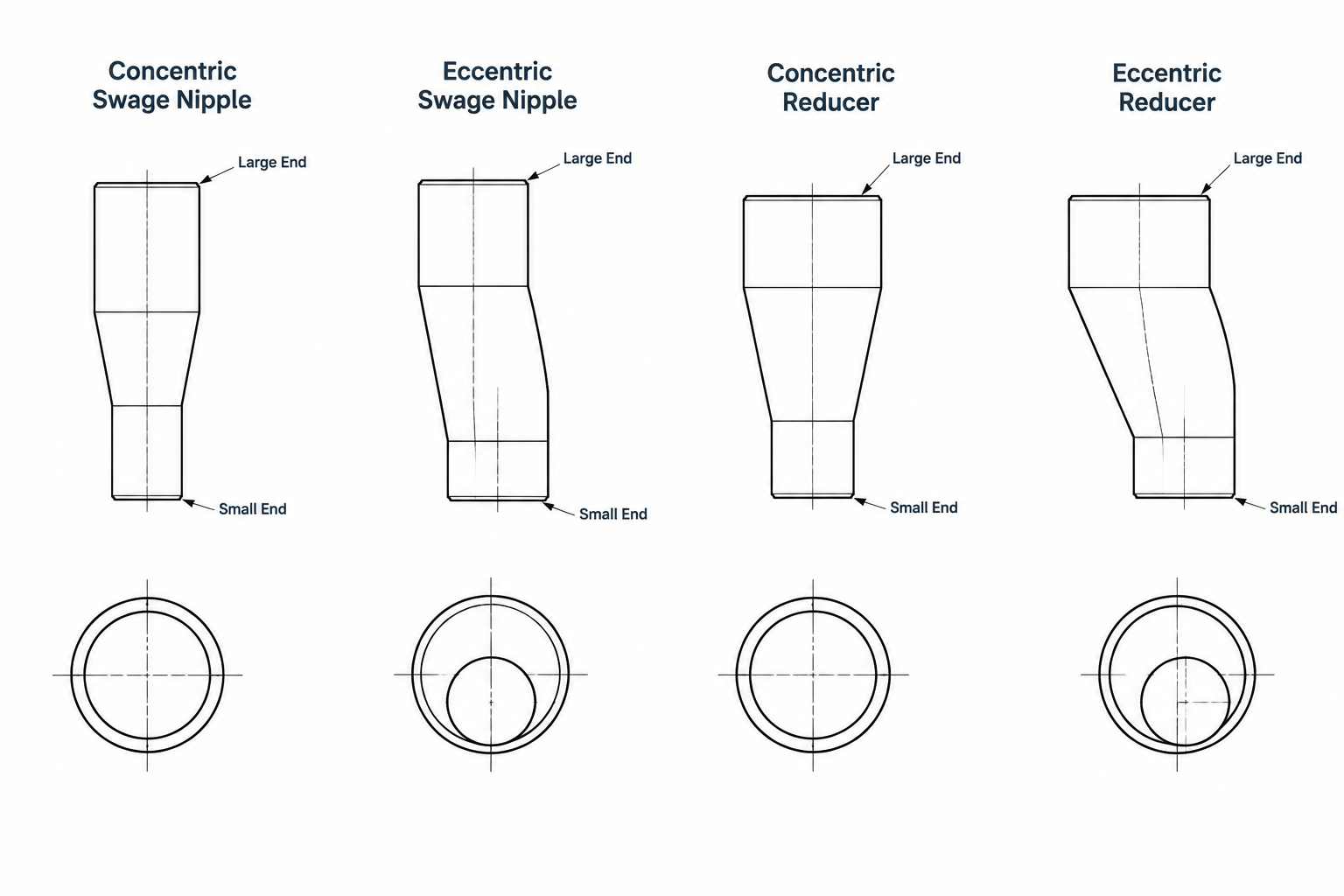
Selection starts at the component ports, not at the tapered silhouette. A swage nipple and a pipe reducer may create the same nominal size transition, but their connection types, catalog identities, layout references, and fabrication requirements can differ.
This guide helps piping designers and drafters distinguish the components, describe each end correctly, and avoid treating visually similar CAD geometry as proof of interchangeability. Final selection must remain consistent with the project piping specification, approved component data, and intended joint arrangement.
A swage nipple and a pipe reducer can perform the same basic function: connecting piping of two different nominal sizes. They are not automatically interchangeable, however. Their end configurations, dimensional references, installation methods, and typical applications can differ substantially.
For a piping designer or drafter, the important question is not simply whether the line changes size. The drawing must also communicate what component creates the transition, how each end connects, which dimensions control the layout, and whether the item belongs to the applicable piping material specification.
This guide explains the practical differences without relying on a specific manufacturer or dimensional table. Actual dimensions, wall thicknesses, end preparations, pressure-temperature suitability, and material requirements must be verified against the governing project documents and applicable product standards.
What Is a Pipe Reducer?
A pipe reducer is a fitting used to transition between two nominal pipe sizes. In process and industrial piping, the term commonly refers to a butt-welding fitting with prepared ends that join directly to adjoining pipe, fittings, or compatible equipment connections.
The two familiar geometric forms are:
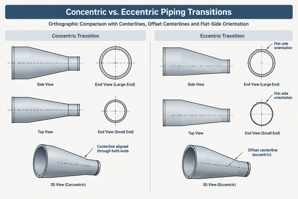
- Concentric reducer: The centerlines of the large and small ends are aligned. The transition is symmetrical around the piping centerline.
- Eccentric reducer: The end centerlines are offset. One side may be arranged to remain flat, depending on the required orientation and service.
A reducer is generally treated as a fitting rather than as a short piece of pipe. Its overall length, outside profile, end diameters, wall requirements, and weld-end details must come from the selected fitting specification or verified manufacturer data.
What Is a Swage Nipple?
A swage nipple is a size-transition component with a relatively direct tapered body between a large end and a small end. Unlike a conventional butt-weld reducer, a swage nipple may be supplied with different connection types at its two ends.
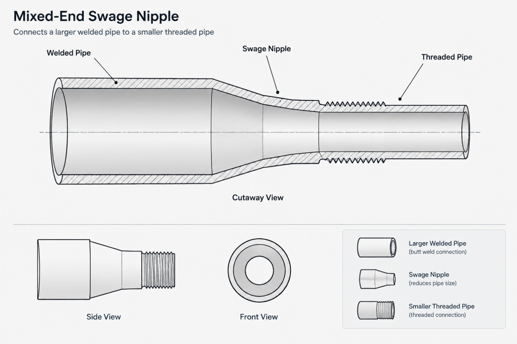
Depending on the piping class and product definition, possible configurations may include:
- Plain or beveled ends for welding
- External threaded ends
- A threaded end combined with a welding end
- Concentric or eccentric body geometry
The word nipple can cause confusion because ordinary pipe nipples are often understood as short pieces of pipe with threaded or prepared ends. A swage nipple is distinguished by its change in nominal size. Its exact construction and end descriptions must be stated rather than inferred from the name alone.
Swage Nipple vs. Pipe Reducer at a Glance
| Comparison point | Swage nipple | Pipe reducer |
|---|---|---|
| Primary function | Changes size, often while adapting connection types | Changes size within a compatible fitting system |
| Common end arrangements | May be threaded, plain, beveled, or mixed | Commonly supplied with butt-welding ends in process piping |
| Geometry | Concentric or eccentric tapered body | Concentric or eccentric reducer profile |
| Typical drawing concern | Correct identification of both end connections | Correct length, orientation, and weld-end compatibility |
| Interchangeability | Must be confirmed by the piping specification | Must be confirmed by the piping specification |
| CAD library behavior | May require connection-specific component variants | Usually selected by size pair, type, wall data, and specification |
Why End Connections Matter More Than the General Shape
Two components may appear nearly identical in a simplified isometric or single-line model while requiring very different field assembly. A reducer with butt-welding ends creates welded joints at both ends. A swage nipple with a threaded small end creates a threaded connection at that location, even if the large end is welded.
That difference affects:
- The number and type of joints shown on the isometric
- Weld numbering and inspection records
- Thread engagement and makeup considerations
- Cut-length calculations for adjoining pipe
- Material takeoff descriptions
- Purchasing and fabrication instructions
- Whether dissimilar end preparations require additional components
A generic tapered symbol is therefore not enough for fabrication documentation. The component description or associated data must identify the end condition at each port.
Typical Reasons to Select One Over the Other
Use of a conventional reducer
A conventional reducer is often appropriate when the size transition occurs within a butt-welded piping run. It provides a recognizable fitting arrangement and can be represented consistently in piping models, isometrics, and bills of material.
An eccentric reducer may be selected where maintaining a particular top, bottom, or side relationship is important. The required orientation should come from the process and layout design, not from a universal drafting rule.
Use of a swage nipple
A swage nipple may be useful where a compact transition or a change in connection type is required. Examples can include instrument branches, vents, drains, utility connections, or other small-bore interfaces, provided the piping specification permits that construction.
This does not mean that a swage nipple is always shorter, stronger, or more suitable than a reducer assembly. Those conclusions depend on the selected product, material, end configuration, service, and governing design requirements.
How to Describe the Component Correctly
Both reducers and swage nipples are normally identified by the large nominal size followed by the small nominal size. The size order alone does not fully define the item.
A useful component description may need to include:
- Large-end nominal size
- Small-end nominal size
- Concentric or eccentric form
- End connection at the large end
- End connection at the small end
- Material or material specification reference
- Wall or schedule-related requirements where applicable
- Applicable piping class or commodity code
For mixed-end swage nipples, use an unambiguous end sequence. A note such as “threaded by beveled” can still be misread unless the drawing, catalog description, or data system clearly associates each connection with the corresponding size.
CAD Modeling and Component-Port Setup
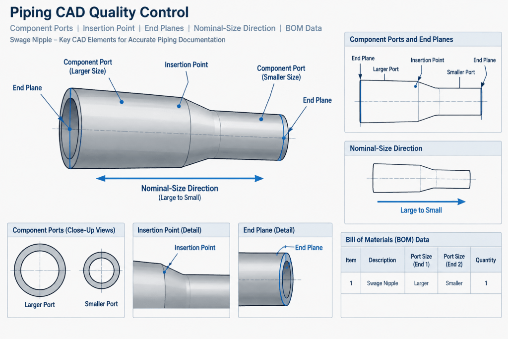
In an intelligent piping model, each component port should carry the correct nominal size and connection type. Treating a mixed-end swage nipple as a generic reducer can cause automated connection checks to accept an invalid joint or generate the wrong adjacent component.
Review the following properties when creating or selecting a catalog item:
- Nominal size assigned to each port
- Port connection type
- Component length reference
- Insertion point and port locations
- Concentric or eccentric offset
- Orientation behavior during placement
- Long description used in the bill of material
- Specification and commodity assignment
The graphics should represent the component clearly, but connection intelligence is equally important. A visually convincing model can still be technically wrong if both ports are coded as butt-welded when one end is threaded.
Dimensioning the Transition
Do not derive a reducer or swage nipple length by scaling a symbol or measuring an unverified CAD block. Use a controlled dimensional source that matches the exact component definition.
For layout and fabrication, distinguish among:
- Component end-to-end length: The distance between the defined end planes or ports.
- Centerline offset: Relevant to eccentric configurations.
- Pipe cut length: The adjoining straight-pipe length after fitting takeouts and connection details are considered.
- Threaded assembly position: The assembled location after the threaded joint is made up according to the project procedure.
A threaded end should not be located by assuming its physical tip represents the final joint position. Likewise, a welding end may require fabrication information not shown in a simplified model. Keep nominal layout geometry separate from detailed end preparation when the drawing purpose does not require both.
Orientation of Eccentric Components
Both reducers and swage nipples can have eccentric geometry. Their flat side may be oriented up, down, or sideways depending on the line function and layout objective.
The orientation should be established from factors such as drainage, vapor-pocket avoidance, pump or equipment requirements, available clearance, and the intended pipe elevation reference. A note, rotation value, section view, or clear graphical representation should remove ambiguity.
Do not assume that a generic “flat side up” or “flat side down” rule applies to every service. Confirm the process requirement and project practice.
Common Drafting and Specification Errors
- Using the names interchangeably: Similar function does not make the components identical.
- Omitting end connections: This is especially risky for mixed-end swage nipples.
- Reversing size order: Inconsistent descriptions can produce purchasing and BOM errors.
- Ignoring eccentric orientation: The model may connect while creating the wrong top or bottom elevation.
- Substituting by geometry alone: Matching overall space does not establish material, wall, connection, or service compatibility.
- Using an unverified block length: Library geometry must be checked against the exact specified component.
- Combining components in the BOM: A reducer, swage nipple, reducing coupling, and reducing bushing should not share one generic description.
Practical Review Checklist
- Confirm that the piping material specification permits the selected component.
- Verify the large and small nominal sizes in the correct order.
- Identify whether the transition is concentric or eccentric.
- Check the connection type at each end independently.
- Verify the controlled end-to-end dimension and port locations.
- Confirm wall and bore compatibility where welding is involved.
- Show eccentric orientation clearly.
- Check adjacent pipe cut lengths and joint representation.
- Ensure the isometric description matches the model properties.
- Keep reducer and swage nipple commodity codes distinct.
Final Takeaway
The key difference between a swage nipple and a pipe reducer is not merely the shape of the taper. A conventional reducer is commonly used as a fitting within a compatible welded piping system, while a swage nipple may provide a transition that also changes the end-connection arrangement.
For reliable CAD and fabrication documentation, define both ports, verify the specified component dimensions, and show eccentric orientation where applicable. Never substitute one transition component for another solely because it fits the same space in the model.
A Document-Controlled Selection Workflow
A reliable comparison should move from the piping specification to the component definition and then to the drawing or model. Starting with an available CAD shape and attempting to justify it afterward can conceal incorrect end connections, dimensions, or commodity assignments.
Establish the required interfaces
Identify what the transition connects at its large and small ends. Record the nominal size, connection type, and required joint representation for each interface independently. This step is particularly important when a swage nipple combines unlike end preparations.
Confirm the permitted component
Check whether the applicable piping class or material specification calls for a reducer, swage nipple, or another reducing component. Similar geometry does not establish equivalent material, wall, bore, end preparation, or service suitability.
Apply controlled dimensional data
Build or select the CAD item using dimensional information that matches the specified product definition. The graphical body, insertion points, ports, end planes, and eccentric offset should agree with that source. Avoid adjusting a generic block merely to fill the available model space.
Coordinate the deliverables
Compare the model, isometric, bill of material, line documentation, and fabrication information before release. The component name, size order, end connections, orientation, and commodity identity should communicate the same selection in every deliverable.
Managing Changes During Design
If a reducer is changed to a swage nipple, or the reverse, treat the revision as more than a graphical substitution. Recheck adjacent pipe cut lengths, joint types, weld or thread representation, port compatibility, eccentric orientation, bill-of-material wording, and specification compliance.
A component that occupies a similar envelope may still alter fabrication scope and field assembly. Keeping the CAD catalog record tied to an approved component definition helps prevent an apparently minor model edit from becoming an undocumented material change.
Frequently Asked Questions
Can appearance alone identify a swage nipple or reducer?
No. A simplified drawing may show both as tapered transitions. Identification should come from the component description, port connection data, piping specification, and controlled dimensional source.
Can a swage nipple replace a reducer when both connect the same nominal sizes?
Not automatically. The piping specification must permit the component, and both end connections, material requirements, dimensional references, wall conditions, and service requirements must be verified.
How should a mixed-end swage nipple be represented in CAD?
Assign the correct nominal size and connection type to each port. The long description and bill-of-material entry should also associate each end condition with the appropriate side of the component.
Does an eccentric transition always have the same orientation?
No. Orientation depends on the process and layout requirements. The model and drawing should show the required rotation or flat-side relationship without relying on an assumed universal convention.
Why should reducers and swage nipples have separate commodity identities?
Separate identities help preserve the correct purchasing description, connection behavior, specification assignment, and fabrication treatment. A generic reducing-component description can hide meaningful differences.
Can an existing CAD block be reused for either component?
Only after its geometry, port locations, connection properties, description, and specification assignment have been checked against the exact selected component. Visual similarity by itself is not adequate validation.