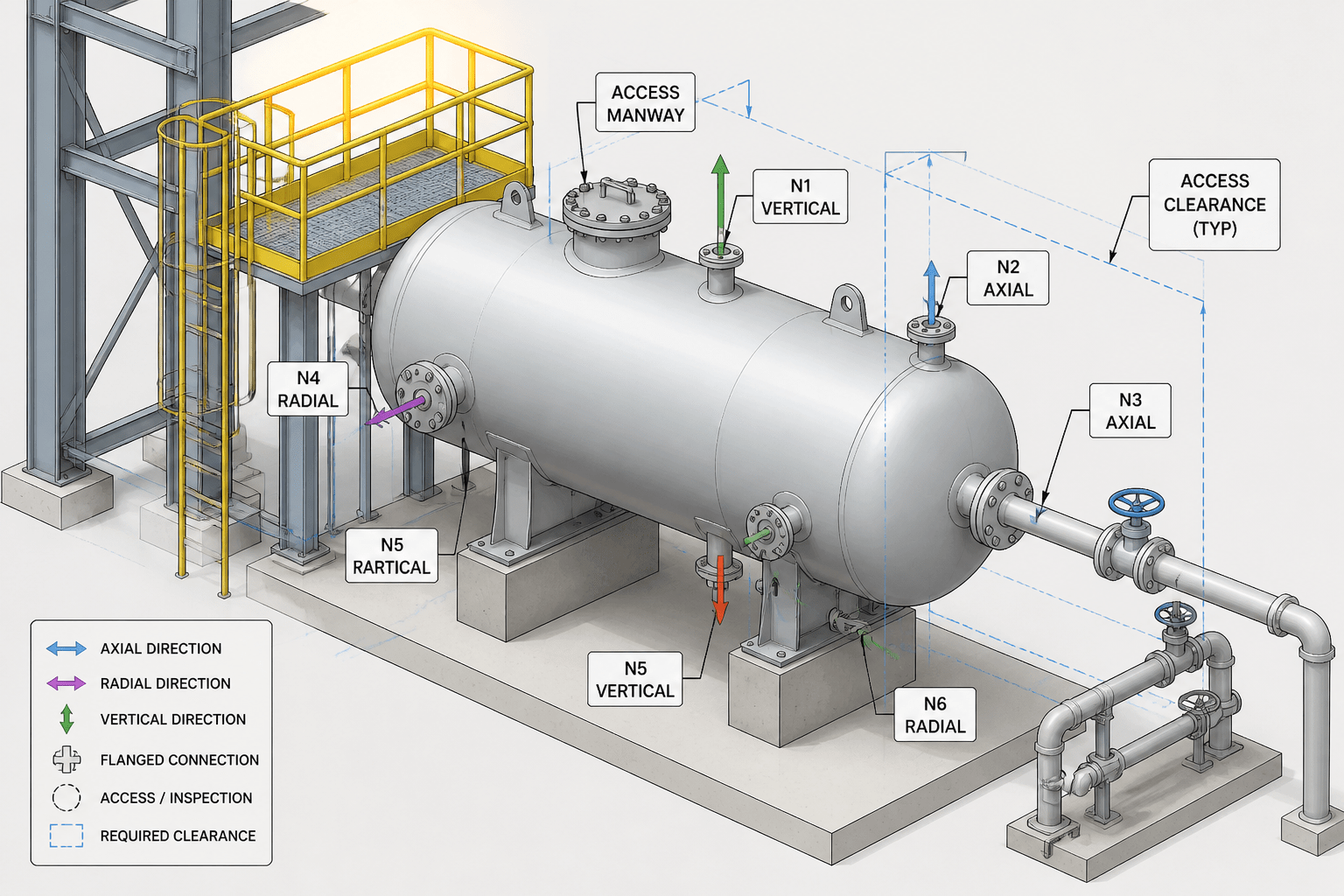
Piping equipment nozzle orientation is a coordination task, not merely a matter of placing a connection symbol in a CAD model. The nozzle establishes where piping meets the equipment, how the line approaches it, and whether the connection remains accessible for assembly, operation, inspection, and maintenance.
This guide explains a practical review method for equipment nozzles on vessels, tanks, pumps, heat exchangers, filters, and related equipment. Use the existing equipment information as the geometry authority, then verify the nozzle location, axis, connection interface, flange rotation, projection, and surrounding clearances before routing the connected line.
Equipment nozzles are the connection points between vessels, tanks, pumps, heat exchangers, filters, and the piping system around them. In CAD, a nozzle is more than a short pipe stub or flange symbol. Its location, orientation, elevation, facing, projection, and connection information directly affect routing, access, maintenance, fabrication, and drawing coordination.
A piping model can appear complete while still containing nozzle problems. A line may connect graphically but approach the wrong side of a nozzle. A flange may be rotated into an inaccessible position. A nozzle elevation may conflict with the equipment outline, platform, insulation, or support steel. The purpose of a nozzle review is to verify the physical and data relationship between the equipment and the piping before the layout becomes difficult to change.
What nozzle orientation means in piping CAD
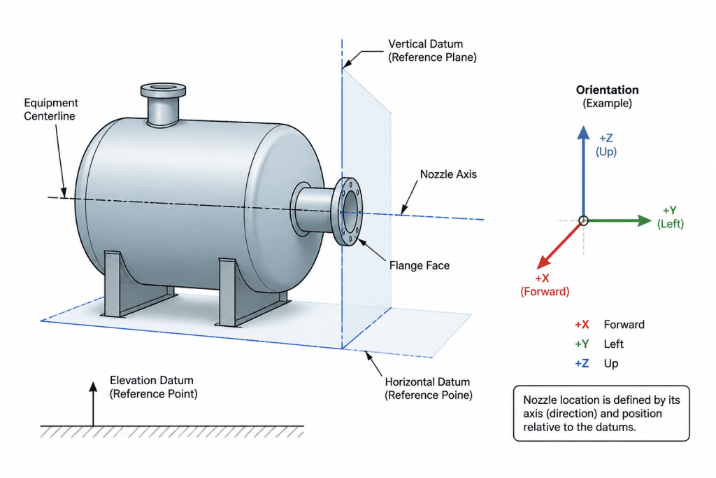
Nozzle orientation describes how a connection is positioned relative to the equipment and the project coordinate system. It commonly includes the nozzle location, centerline elevation, direction of the nozzle axis, flange rotation, connection type, and projection from the equipment surface.
The nozzle axis is especially important. A nozzle may point horizontally, vertically upward, vertically downward, radially, tangentially, or in another defined direction. The axis establishes how the connected pipe should approach the equipment. The flange face is usually normal to that axis, but the bolt-hole orientation still needs separate attention.
Do not treat an equipment nozzle as a generic connection point. Its position may be controlled by process requirements, vessel internals, heat-transfer surfaces, access platforms, lifting clearances, removable covers, or equipment vendor information. The piping layout should preserve that design intent rather than relocating the connection for drafting convenience.
Information to collect before modeling
Before creating or modifying a nozzle in a CAD model, gather the latest equipment and piping information available for the project. The exact document names vary, but the review should cover the following data:
- Equipment identification and orientation reference.
- Nozzle identification, service, size, and connection type.
- Nozzle center location and elevation relative to the equipment datum.
- Nozzle axis direction and flange-face orientation.
- Projection, neck arrangement, or other vendor-defined connection geometry.
- Required insulation, cladding, lining, or removable-cover allowances.
- Connected line number, piping class, material information, and specification boundary.
- Access, maintenance, removal, lifting, and operating-space requirements.
- Equipment support, foundation, platform, ladder, and structural interfaces.
Use the project’s controlled equipment drawing, vendor model, or approved data source as the geometry authority. If the equipment model and piping document show different nozzle positions, do not silently choose one. Record the discrepancy and obtain a controlled resolution.
Separate the nozzle data into geometry and connection data
A reliable workflow distinguishes the physical location of the nozzle from the information that defines the connected piping. Both are required, but they are checked differently.
| Data group | Typical checks | Common CAD consequence |
|---|---|---|
| Location | Equipment datum, coordinates, elevation, radial or tangential position | Incorrect pipe start point or equipment clash |
| Orientation | Nozzle axis, flange face, rotation, upward or downward direction | Forced routing, twisted connection, or inaccessible bolting |
| Connection | Flange, butt-weld, threaded, socket-weld, sanitary, or special connection | Wrong end treatment, gasket interface, or BOM item |
| Projection | Neck length, flange projection, face location, insulation interface | Incorrect takeout and inaccurate spool geometry |
| Service and line data | Line number, specification, temperature or pressure design inputs | Specification break or item-data inconsistency |
This separation helps identify the source of an error. For example, a pipe that stops at the wrong location has a geometric problem, while a correct connection modeled with the wrong flange type has a component-data problem.
Establish a consistent equipment coordinate reference
Equipment nozzles are often described using a local reference system, while piping drawings use plant coordinates and elevations. The local and global systems must be related clearly in the CAD model.
First, identify the equipment orientation reference. This may include a designated zero-degree direction, an equipment centerline, a support axis, or a project north reference. Then confirm how nozzle angular positions, elevations, and offsets are measured. Avoid interpreting a vendor’s clocking or angular notation from appearance alone; the reference direction and viewing side matter.
For vessels and tanks, check whether a nozzle position is described around a shell, head, or skirt and whether the stated elevation refers to the nozzle centerline, face, or another datum. For horizontal equipment, verify which end is the front or channel end and how the equipment axis is represented in the model. These details prevent mirrored layouts and reversed equipment connections.
Model the connection at the correct interface
The piping model should terminate at the defined connection interface, not at an approximate point on the equipment outline. For a flanged nozzle, this may mean coordinating the pipe-side flange with the specified flange face and gasket interface. For a welded connection, the model may need to represent the equipment-side weld location or the agreed piping termination point. The project modeling convention should control the level of detail.
Keep the connection interface unambiguous in plans, elevations, and isometrics. A line that visually touches equipment but does not identify the actual connection point can create uncertainty during fabrication and review. Use the nozzle tag or connection identifier consistently wherever the connection is referenced.
Check orientation before routing the connected line
Once the nozzle is modeled, inspect the proposed route in the direction normal to the connection face and in the surrounding orthographic views. This check should answer practical questions:
- Does the pipe approach the nozzle without an unintended twist or sharp geometric transition?
- Is the connected flange or fitting oriented consistently with the nozzle?
- Are bolt access and gasket installation areas visible and reachable?
- Does the route avoid equipment nozzles, manways, removable covers, instruments, and access platforms?
- Is there enough space for insulation, coating, supports, and field assembly?
- Does the line leave the equipment in a direction that supports operation and maintenance?
Do not solve every orientation issue by adding an elbow immediately at the equipment. An elbow may be appropriate, but it can also introduce unnecessary stress, obstruct access, or create a difficult spool. Review the nozzle direction, line route, support concept, and equipment access together.
Coordinate nozzle orientation with maintenance and access
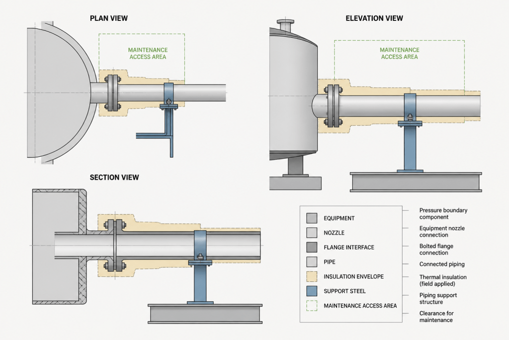
A nozzle can be geometrically correct and still be poorly coordinated. Flanged connections need space for bolt installation and removal. Valves, strainers, spectacle devices, and other inline items may need operating or maintenance clearance. Equipment openings and removable components require a path for withdrawal or lifting.
Review the nozzle and first section of connected piping with the equipment maintenance envelope. Pay particular attention to downward-facing and upward-facing connections, which may interact with drains, platforms, grating, structural members, or lifting paths. Also check whether insulation or personnel-protection features change the usable clearance around the connection.
Review the nozzle in multiple drawing views
Nozzle errors are often hidden when reviewed in only one view. Use a coordinated set of views:
- Plan view: Check radial position, horizontal routing, equipment orientation, and nearby obstructions.
- Elevation view: Check centerline elevation, vertical direction, platforms, foundations, and slope transitions.
- Section view: Check projection, flange-face location, internal or external clearances, and access depth.
- Isometric view: Check the practical connection sequence, fittings, dimensions, welds, and item identification.
- Three-dimensional model view: Check the combined relationship between piping, equipment, structure, insulation, and maintenance space.
Dimension the nozzle location from stable references. Equipment centerlines, tangent lines, base elevations, and defined datum planes are generally easier to verify than arbitrary nearby geometry. Make sure the drawing states what each elevation or offset represents.
Common nozzle detailing mistakes
- Using a generic nozzle block without updating its axis, projection, or connection data.
- Mirroring a vessel or exchanger without checking nozzle tags and orientation references.
- Connecting the pipe to an equipment outline instead of the defined interface.
- Showing a flange face correctly but rotating the bolt pattern incorrectly.
- Ignoring insulation or cladding when checking access and clearances.
- Routing directly into a nozzle without reviewing supports, flexibility, and equipment load inputs.
- Allowing the nozzle tag, line number, and equipment identifier to disagree between drawings and the model.
- Changing a vendor-controlled nozzle position in CAD without documenting the change.
A practical final review checklist
Before issuing a piping layout or isometric, verify each equipment connection systematically. Confirm the nozzle tag, equipment reference, location, elevation, axis direction, flange-face orientation, connection type, projection, and connected line data. Then review access, insulation, supports, structural interfaces, and maintenance space.
Finally, compare the model against the latest controlled equipment information and check the same connection in every affected drawing view. A nozzle review is complete only when the geometry, component data, labels, dimensions, and surrounding layout tell the same story. This approach reduces late rerouting and gives designers, fabricators, reviewers, and field personnel a dependable connection reference.
Why nozzle orientation deserves an early CAD review
Nozzle errors often propagate through the entire piping layout. A misplaced centerline can affect routing and dimensions, while an incorrect axis or flange rotation can create access problems even when the model appears connected. Reviewing the connection before detailed routing makes discrepancies easier to identify and resolve.
The most useful approach is to treat each nozzle as a coordinated interface between equipment data and piping data. The equipment side defines the controlled location and orientation. The piping side must then reflect the connection type, line information, routing intent, support concept, and required working space.
How to use this guide during design review
- Start with the latest controlled equipment information and identify the applicable equipment datum.
- Separate geometric checks from connection-data checks so the source of an error is clear.
- Review the nozzle in plan, elevation, section, isometric, and three-dimensional views as applicable.
- Check the connection together with access, insulation, structure, supports, and maintenance requirements.
- Resolve conflicts through documented project coordination rather than silently changing vendor-controlled geometry.
The source content below provides the detailed workflow, review questions, common mistakes, and final checklist needed to make nozzle information consistent across the model and drawings.
Frequently Asked Questions
What is equipment nozzle orientation in piping CAD?
It is the coordinated description of a nozzle’s position, elevation, axis direction, flange-face orientation, connection type, and projection relative to the equipment and project coordinate system.
Why is the nozzle axis important?
The nozzle axis determines how the connected pipe approaches the equipment. If the axis is wrong, the route may require an unintended twist, create awkward fittings, or interfere with access and maintenance space.
Should a nozzle be modeled as a generic pipe stub?
No. A generic representation can omit important information such as the connection interface, flange rotation, projection, and equipment reference. Model the nozzle according to the project convention and controlled equipment information.
What should be checked before routing from an equipment nozzle?
Confirm the equipment datum, nozzle location, elevation, axis, flange-face orientation, connection type, projection, connected line data, and nearby access or maintenance requirements. Then review the proposed route in the relevant drawing views.
How can nozzle orientation problems be found in CAD?
Compare the model with the controlled equipment source and inspect the connection in coordinated plan, elevation, section, isometric, and three-dimensional views. Look for incorrect approach direction, inaccessible bolting, clashes, unclear interfaces, and inconsistent identification.
Who controls the nozzle location when project documents disagree?
The discrepancy should be recorded and resolved through the project’s controlled coordination process. Do not silently select a convenient position or alter vendor-controlled geometry without approval.