Tag: piping design

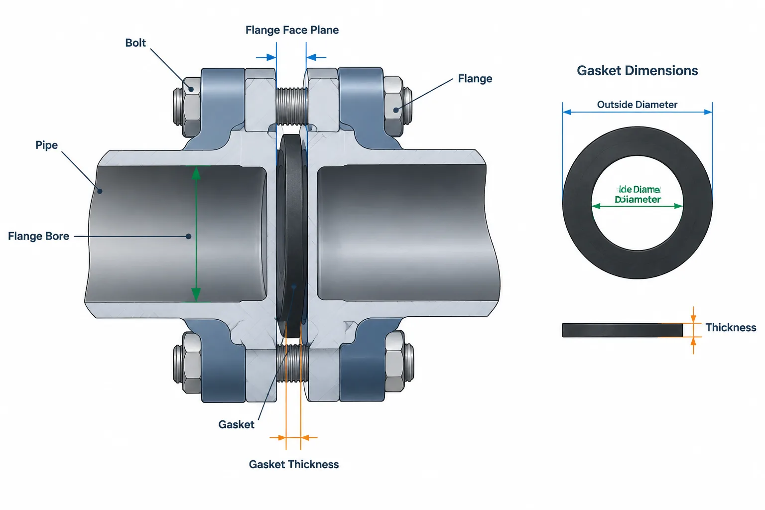
  • Flange Gasket Dimensions in Piping CAD: ID, OD, Thickness, and Centering

    Flange Gasket Dimensions in Piping CAD: ID, OD, Thickness, and Centering

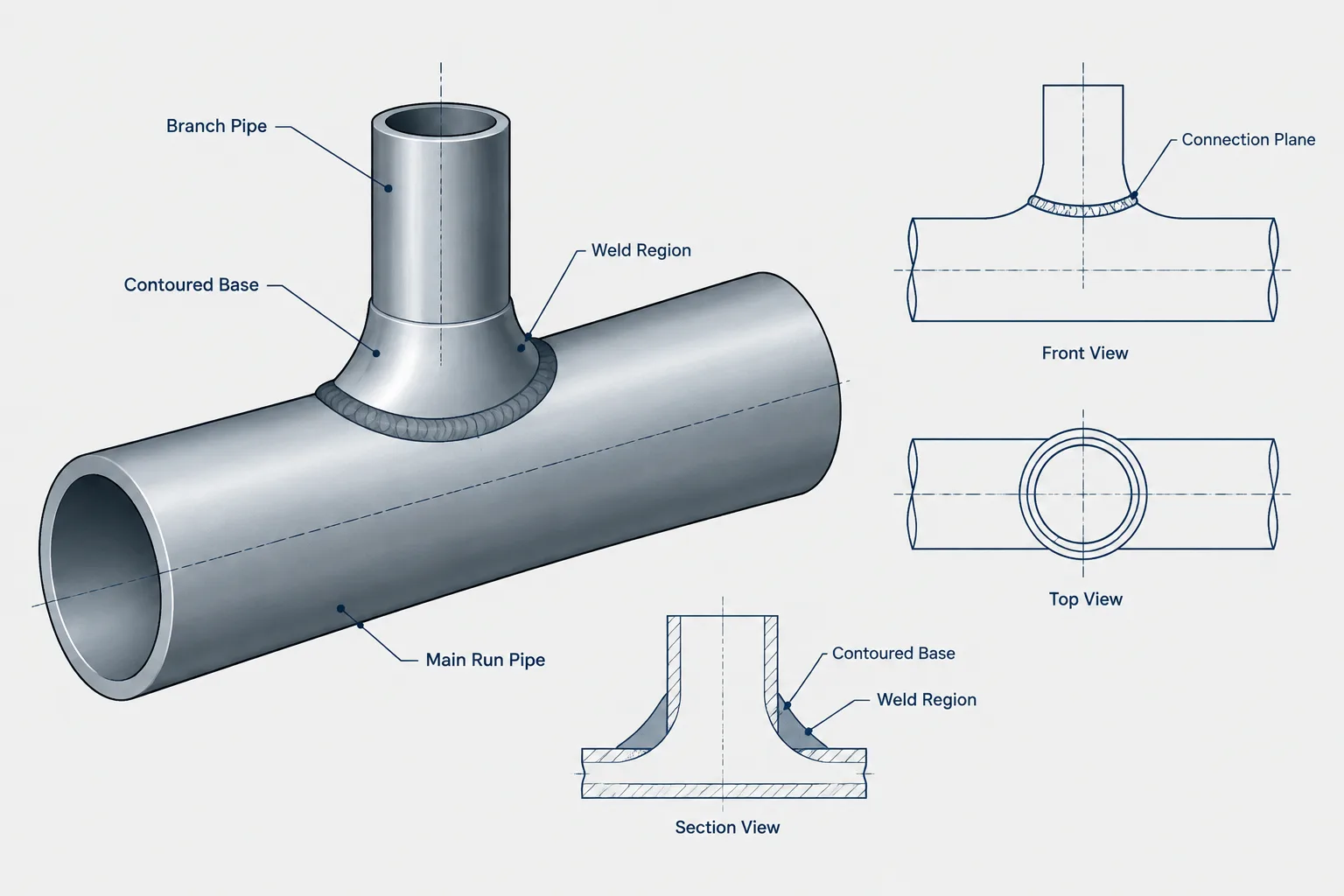
  • Branch Outlet Fittings in Piping CAD: Run Size, Branch Size, End Type, and Model Control

    Branch Outlet Fittings in Piping CAD: Run Size, Branch Size, End Type, and Model Control

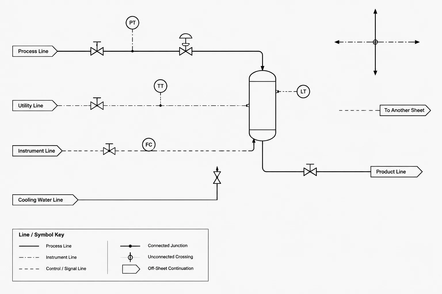
  • P&ID Line Crossings and Connections: How to Avoid False Junctions in CAD

    P&ID Line Crossings and Connections: How to Avoid False Junctions in CAD

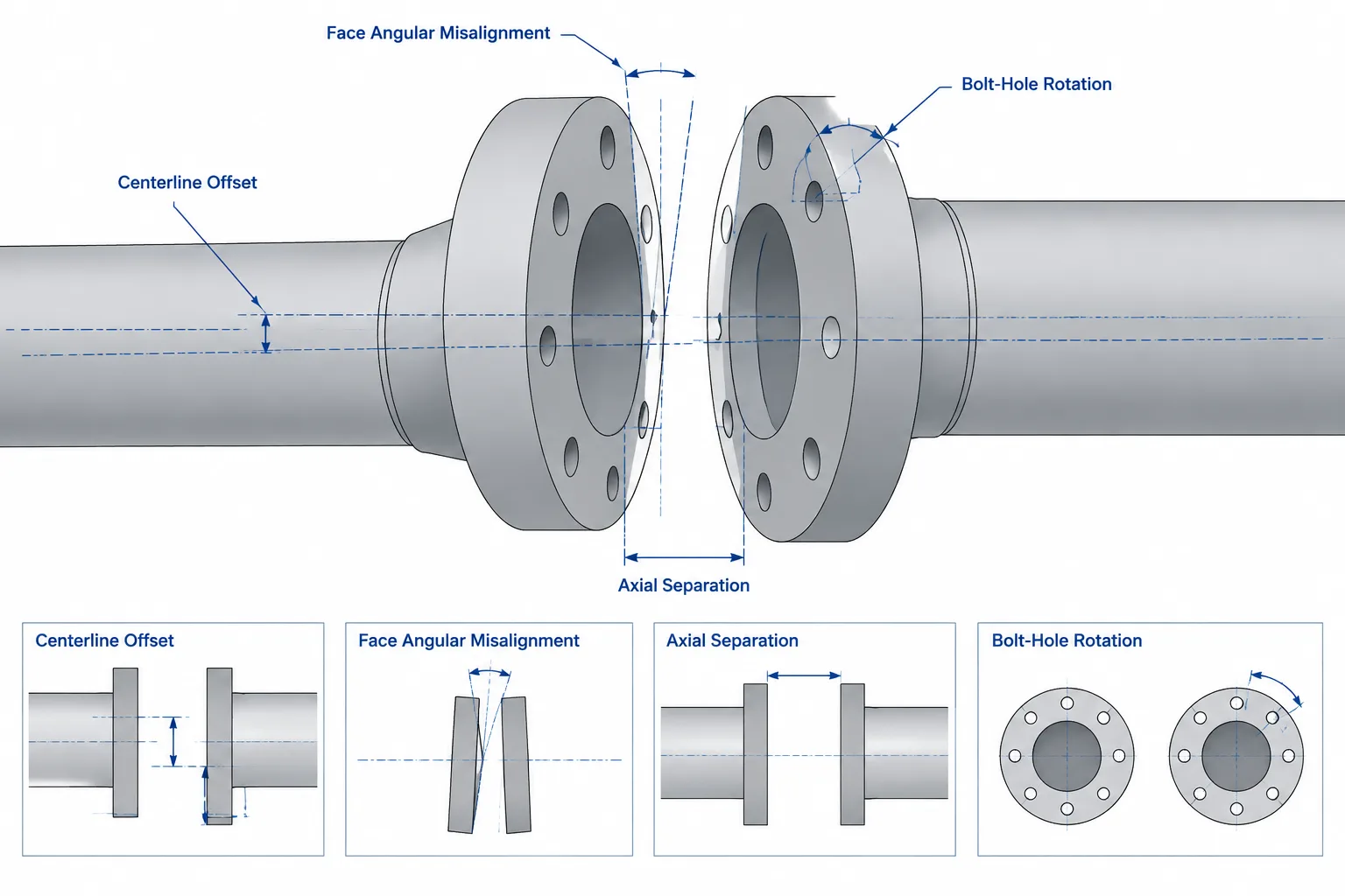
  • Flange Alignment in Piping CAD: Offset, Angular Error, Bolt-Hole Rotation, and Fit-Up

    Flange Alignment in Piping CAD: Offset, Angular Error, Bolt-Hole Rotation, and Fit-Up

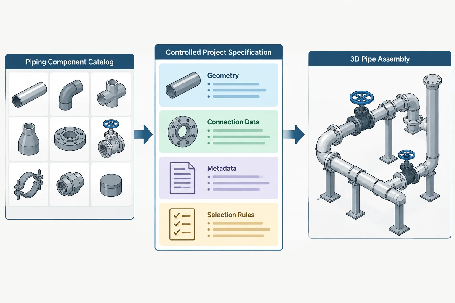
  • Piping CAD Catalogs vs. Project Specifications: Geometry, Selection Rules, and Data Control

    Piping CAD Catalogs vs. Project Specifications: Geometry, Selection Rules, and Data Control

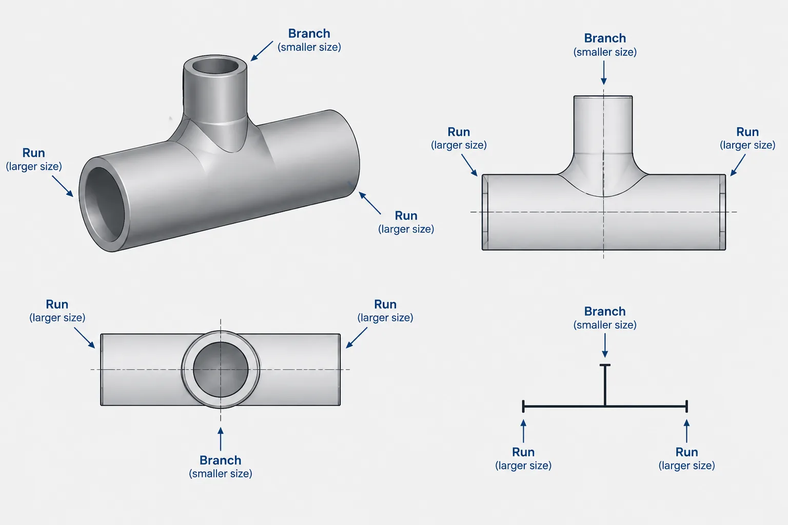
  • How to Read Reducing Tee Sizes: Run, Branch, and CAD Catalog Mapping

    How to Read Reducing Tee Sizes: Run, Branch, and CAD Catalog Mapping

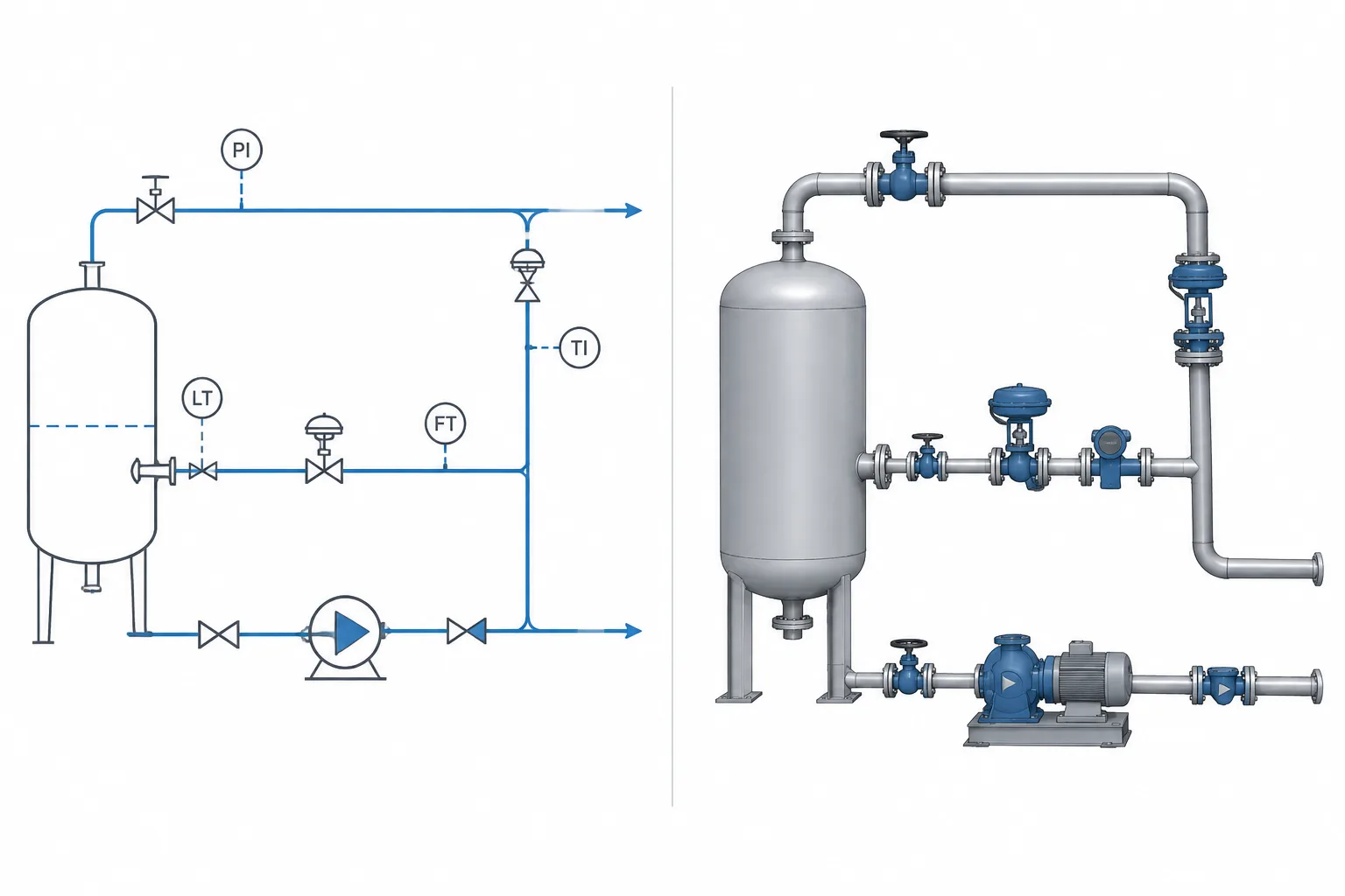
  • P&ID Symbols vs. 3D Piping Models: Why Functional Diagrams and Physical Geometry Differ

    P&ID Symbols vs. 3D Piping Models: Why Functional Diagrams and Physical Geometry Differ

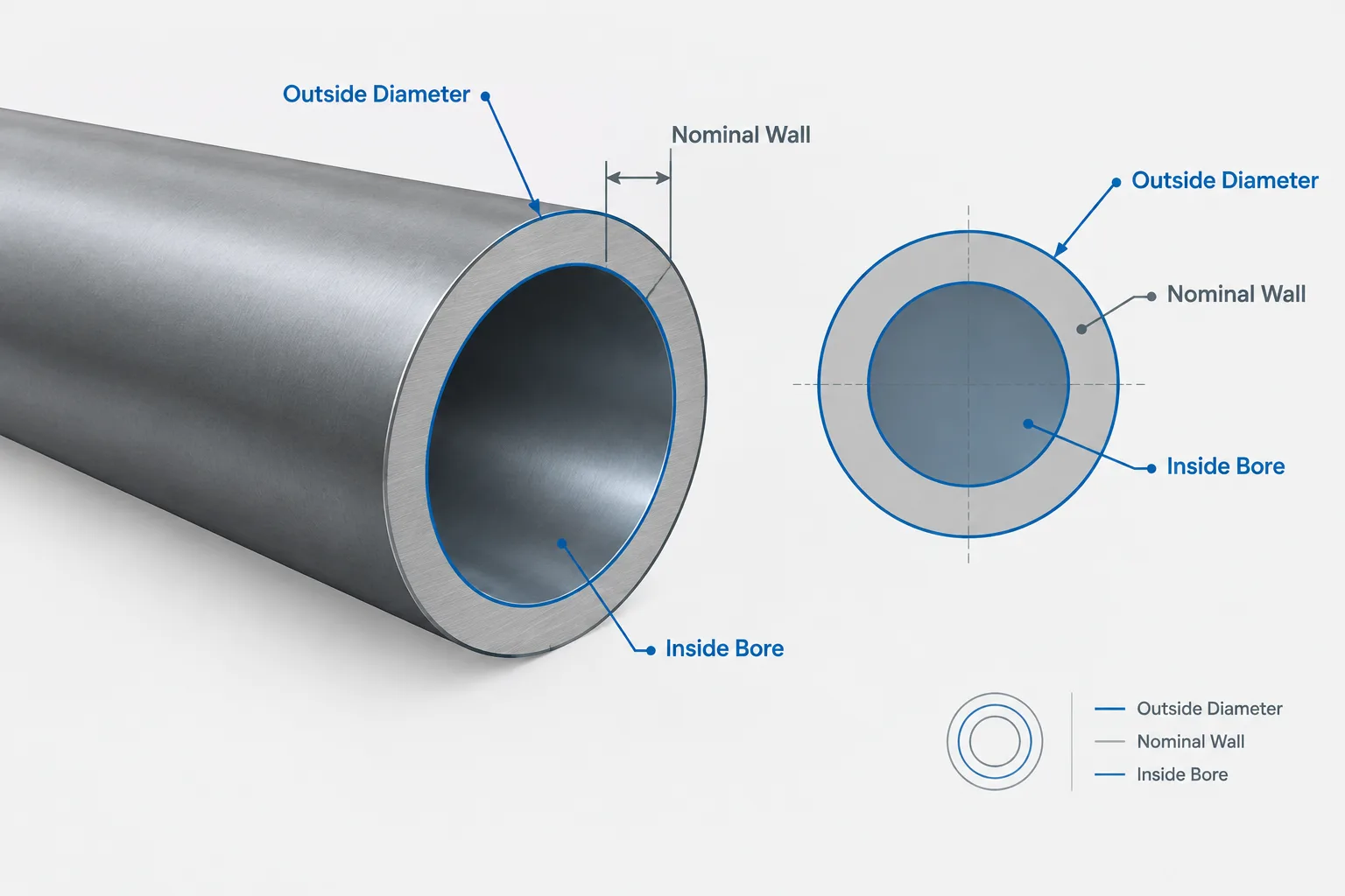
  • Pipe Mill Tolerance in Design and CAD: Nominal Wall, Minimum Wall, and Model Geometry

    Pipe Mill Tolerance in Design and CAD: Nominal Wall, Minimum Wall, and Model Geometry

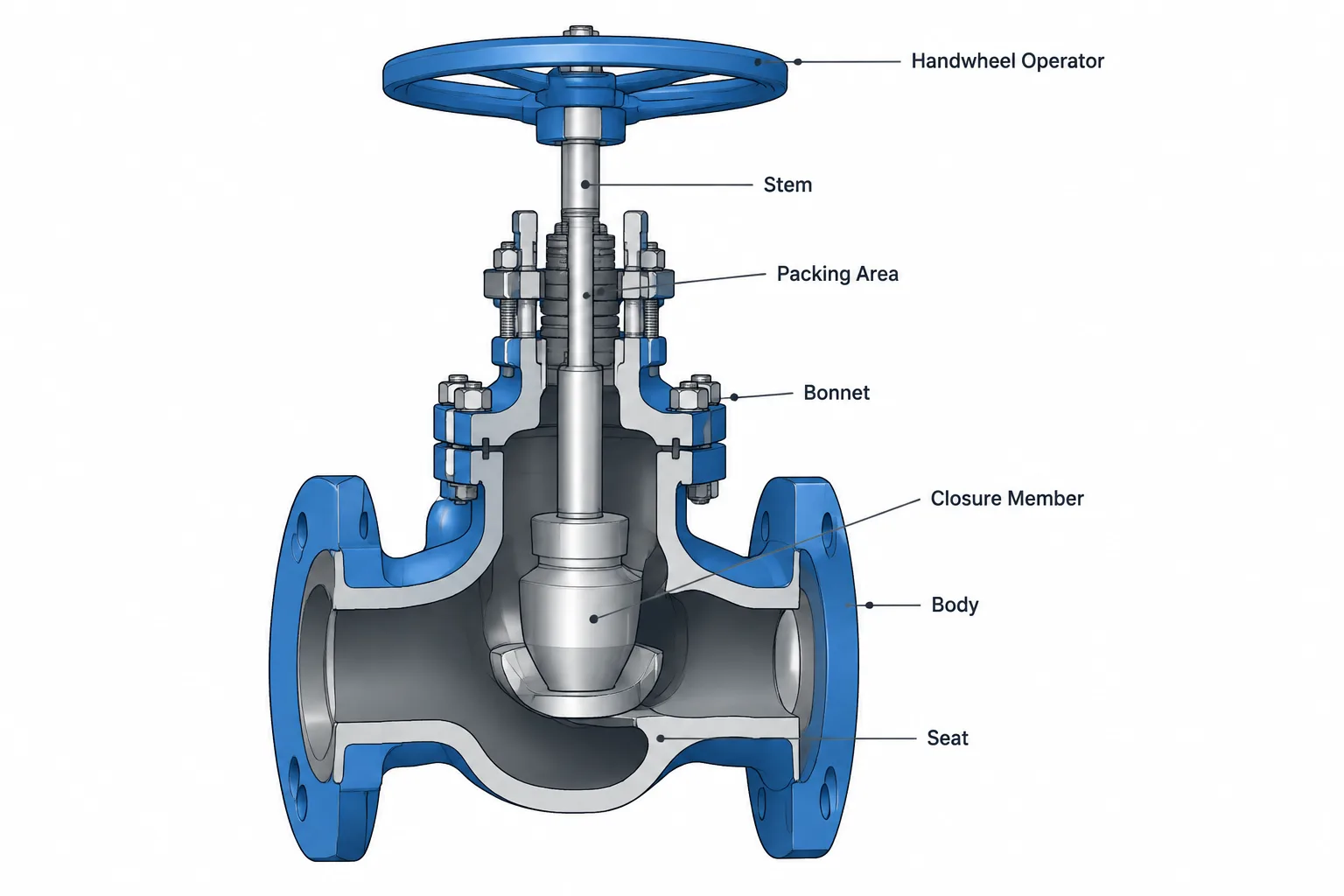
  • Valve Body, Bonnet, and Trim: What the Terms Mean in Piping Documentation and CAD

    Valve Body, Bonnet, and Trim: What the Terms Mean in Piping Documentation and CAD