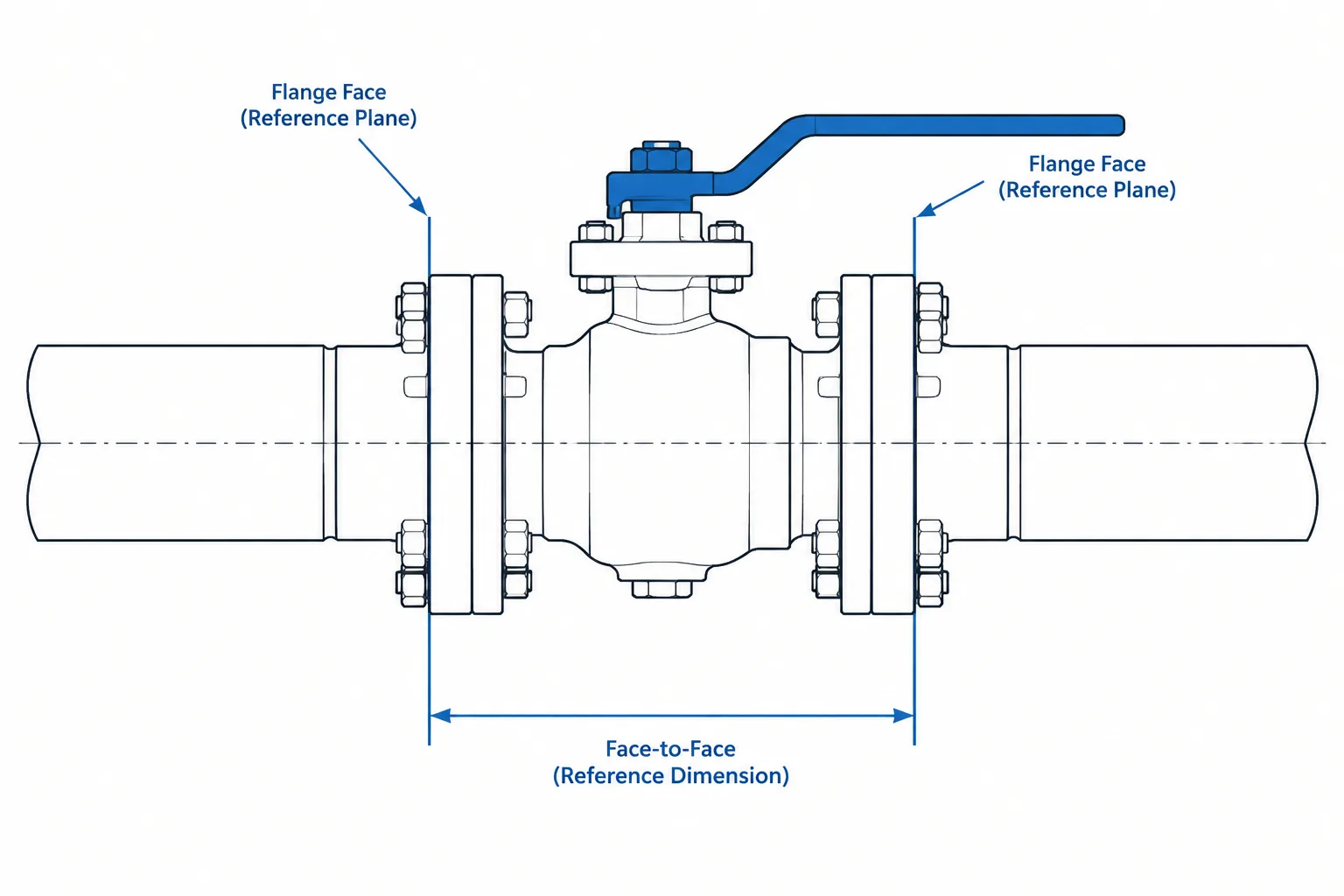
Valve face-to-face dimensions are connection-control data, not merely catalog body measurements. This guide explains how to interpret the controlling planes, distinguish face-to-face from end-to-end and overall length, and apply the correct geometry when laying out piping or evaluating a replacement valve.
Use the concepts with the project specification, approved valve data, applicable dimensional requirements, and the actual joint arrangement. A visually convincing CAD component should remain identified as preliminary until its connection geometry has been verified for the intended deliverable.
A valve may have the correct nominal pipe size, pressure class, material, and end-connection type yet still fail to fit an existing piping gap. The missing check is often its face-to-face or end-to-end dimension.
These dimensions define the axial space occupied by the valve between specified connection reference planes. They affect pipe cut lengths, flange locations, equipment clearances, support positions, and the possibility of replacing one valve with another. In CAD, using the wrong reference planes can create an assembly that looks aligned while remaining dimensionally unsuitable for fabrication or installation.
What Is a Valve Face-to-Face Dimension?
For a valve with flanged ends, the face-to-face dimension is generally the axial distance between the two designated flange-face reference planes. It represents the installed length of the valve itself, not the total length of the surrounding joint assembly.
The term is most commonly associated with flanged and wafer-style valves. However, the exact measurement convention must be confirmed for the applicable valve type, facing, dimensional standard, and manufacturer. A catalog outline may show a body length, overall length, or another dimension that resembles face-to-face but uses different endpoints.
Face-to-face should not be confused with:
- Overall length: the maximum physical length of the valve or assembly, which may include projecting ends or accessories.
- Center-to-face: a dimension from the valve centerline or another datum to one connection face.
- Flange thickness: the axial thickness of an individual flange, not the complete valve length.
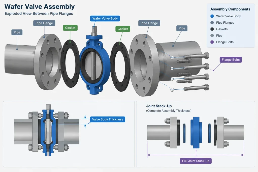
- Joint stack-up: the combined installed space associated with faces, gaskets, companion flanges, and any other joint elements.
- Operator envelope: the space required by a handwheel, lever, gearbox, actuator, or stem movement.
Face-to-Face vs. End-to-End
Face-to-face and end-to-end both describe axial valve length, but they are normally associated with different end configurations.
| Valve connection | Common dimensional term | Typical reference concept | Main CAD concern |
|---|---|---|---|
| Flanged | Face-to-face | Between designated flange faces | Locate mating flange planes correctly |
| Butt-weld | End-to-end | Between weld-end extremities or specified end planes | Control pipe cut length and weld locations |
| Wafer or flangeless | Face-to-face | Across the valve body between mating sides | Account for the complete installed flange assembly |
| Threaded or socket-weld | End-to-end or manufacturer-defined length | Across physical ends, with separate engagement or socket geometry | Do not derive cut length from overall length alone |
The terminology used on a supplier drawing is important, but the dimension arrows are more important. Designers should identify exactly where the extension lines terminate rather than relying only on the dimension label.
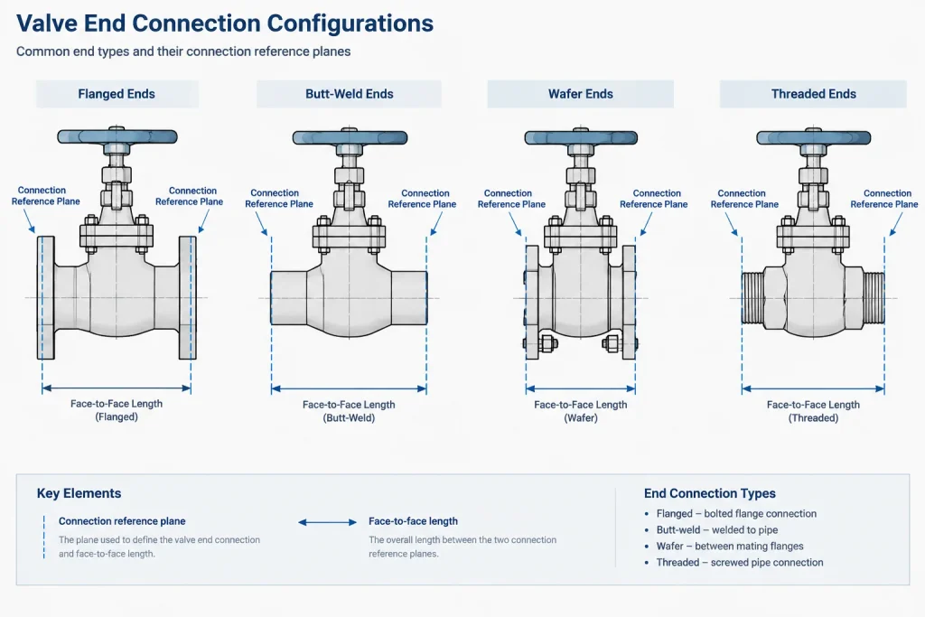
Why End Connections Change the Reference Planes
Flanged valves
A flanged valve is positioned between mating flanges. Its face-to-face dimension controls the nominal axial gap between the valve connection faces, but the piping model must also represent the intended facing arrangement and gasket strategy.
Do not assume every flange-facing configuration uses an interchangeable measurement convention. Raised faces, flat faces, and ring-joint arrangements have different physical contact features. The controlling product drawing or applicable dimensional document should establish the measurement planes.
Butt-weld valves
For a butt-weld valve, the end-to-end dimension controls the distance between weld ends. The model also needs the correct weld-end bore and preparation where that detail matters. A generic valve body with a plausible overall length is not enough for spool fabrication.
Pipe cut lengths should be developed from the specified weld planes and fitting takeoffs. They should not be adjusted informally to compensate for an unverified valve model.
Wafer and flangeless valves
A wafer valve is installed between line flanges, so the valve body thickness is only one part of the complete assembly. Gaskets, flange faces, bolting, centering features, and any restrictions on adjacent flange geometry must be evaluated separately.
A common modeling error is to treat the wafer valve thickness as the full joint length while omitting the adjacent gasket or flange reference relationships. Another is to reuse one generic wafer-valve body for several valve designs whose installed lengths differ.
Threaded and socket-weld valves
Threaded and socket-weld valves require special care because physical end-to-end length does not directly reveal the final pipe cut length. Thread engagement, makeup position, socket depth, assembly gap requirements, and manufacturer geometry can all influence the result.
For layout models, simplified geometry may be adequate. For fabrication-controlled deliverables, the connection details and cut-length method must be explicitly defined.
Standardized Length Does Not Mean Universal Length
Valve face-to-face dimensions are often governed by recognized dimensional standards or established product patterns. That improves interchangeability, but it does not mean that every valve of the same nominal size has the same length.
The applicable dimension can vary with factors such as:
- Valve type and body pattern
- Nominal size
- Pressure class or product rating designation
- Flanged, butt-weld, wafer, threaded, or socket-weld ends
- Long-pattern, short-pattern, or other defined construction
- Port and internal construction
- Special linings, extended bodies, or proprietary designs
- The dimensional standard or manufacturer series being used
A standards-based generic component can be useful during design, but procurement may introduce a product with different dimensions unless dimensional compliance is part of the purchase requirements. Project teams should distinguish between a preliminary standard-pattern envelope and a vendor-confirmed model.
How Face-to-Face Controls Pipe Cut Length
Consider a flanged valve between two pipe spools. The distance between fixed piping datums must accommodate the valve, mating flanges, gaskets, and the pipe or fitting segments on both sides. If the valve face-to-face length changes, at least one adjacent dimension must also change unless the assembly includes an intentional field-fit provision.
The same principle applies to butt-weld valves. A longer end-to-end dimension reduces the available straight-pipe length between fixed weld locations; a shorter valve increases it. Replacing a valve in the CAD model without recalculating adjacent spool dimensions can leave the drawing inconsistent with the geometry.
Designers should also avoid dimensioning the same axial chain in several conflicting ways. A controlled datum-to-datum dimension combined with component reference data is generally safer than a closed chain of redundant dimensions.
A Practical CAD Modeling Workflow
- Identify the end connection. Confirm whether the valve is flanged, butt-weld, wafer, threaded, socket-weld, or another configuration.
- Establish connection datums. Create clear planes at the actual faces, weld ends, or manufacturer-defined connection points.
- Assign the dimensional source. Record whether the component uses a project-standard dimension, a recognized dimensional pattern, preliminary vendor data, or certified supplier information.
- Model axial length parametrically. Drive the body placement from the connection planes rather than stretching graphics by eye.
- Separate body geometry from access geometry. The operator, stem, actuator, removable cover, and maintenance space should not redefine the face-to-face dimension.
- Check adjacent joints. Verify gasket locations, companion flanges, weld planes, bolting space, and nearby fitting takeoffs.
- Update deliverables together. When valve length changes, review the model, isometrics, spool drawings, bills of material, support locations, and interference results.
Replacement and Interchangeability Checks
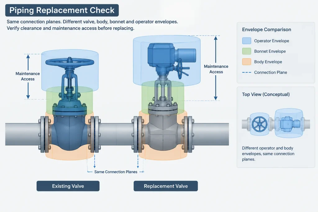
A replacement valve should not be accepted as dimensionally interchangeable based only on line size and connection label. The review should compare the actual connection datums and the installed assembly.
At minimum, verify:
- Face-to-face or end-to-end dimension
- End-connection type and facing
- Flange drilling or weld-end compatibility
- Bore and port geometry where flow or transition details matter
- Stem and operator orientation
- Actuator, handwheel, and lever envelope
- Cover, seat, stem, and actuator removal space
- Flow direction and required installation orientation
- Nearby support, insulation, structure, and access constraints
Even when the axial dimension matches, a replacement may have a different body bulge, bonnet height, operator location, or maintenance envelope. Dimensional interchangeability is therefore broader than a single face-to-face value.
Common CAD and Drawing Errors
- Measuring from flange backs instead of the specified connection faces
- Using overall body length as face-to-face length
- Ignoring facing details when defining reference planes
- Scaling a valve symbol or block to fit an available gap
- Assuming all valves of one size and class share one length
- Omitting gasket and mating-flange relationships from a wafer assembly
- Replacing a preliminary valve without updating pipe cut lengths
- Showing a vendor-confirmed part number with generic, unverified geometry
- Checking the body for clashes while ignoring operator and maintenance space
What Drawings and Data Records Should Communicate
The 3D model does not need to display every internal valve feature, but its connection datums and controlling dimensions must be trustworthy for the intended use. Component metadata should identify the valve type, end connection, size designation, rating or class designation, dimensional basis, and verification status.
Fabrication drawings should dimension piping from controlled faces, weld points, centerlines, or project datums. If a valve dimension remains subject to supplier confirmation, the drawing and project workflow should communicate that status instead of presenting the geometry as final.
Valve face-to-face dimensions are simple in concept but critical in practice. Treating them as controlled connection geometry—rather than merely a body length—helps prevent incorrect spool dimensions, failed replacements, flange misalignment, and avoidable field modifications.
Turning Valve Geometry Into a Controlled Design Record
A reliable valve model should communicate both its geometry and the authority behind that geometry. The component record should distinguish a standard-pattern assumption from supplier-confirmed information so that downstream users understand whether pipe cut lengths, spool dimensions, and support locations are ready for release.
Use connection planes as the stable interface
Body outlines may change as supplier information develops, but the piping model should remain organized around defined connection planes. This makes it easier to replace preliminary geometry without shifting unrelated piping or concealing a dimensional change through graphical stretching.
Separate fit checks from product acceptance
Matching the available axial gap is only one part of replacement review. The accepted product must also satisfy the specified connection, facing, bore, orientation, operating envelope, maintenance access, and project requirements. CAD fit does not by itself confirm technical interchangeability.
Apply change control to dimensional updates
When verified valve information differs from the preliminary model, record the change and review every dependent deliverable. The review should follow the dimension chain into adjacent spools, flange or weld locations, supports, access zones, insulation clearances, material records, and fabrication drawings.
Confirm field conditions for existing systems
Existing drawings and legacy models may not represent the installed condition accurately. Replacement work should use verified field information where required by the project, with clear identification of the measured datums. An available space measured between convenient physical points may not be the same as the specified valve connection-plane distance.
Frequently Asked Questions
Does a matching face-to-face dimension guarantee that a replacement valve will fit?
No. It confirms only one axial relationship. Connection details, flange or weld compatibility, body clearance, operator orientation, maintenance access, flow direction, and nearby piping or structure must also be checked.
Can valve face-to-face length be inferred from nominal pipe size and pressure class?
Not safely. Valve type, body pattern, end connection, dimensional basis, construction, and manufacturer series can affect the controlling length. Use verified dimensional data rather than estimating from size and class alone.
Should gasket thickness be included in the valve face-to-face dimension?
The valve dimension and the complete joint stack-up should be treated separately. Gaskets and mating components must be included according to the intended joint arrangement, while the valve length must use its specified reference planes.
Where should the origin of a valve CAD component be placed?
There is no single origin location that suits every CAD system, but the component should have stable connection points tied to the actual face or end planes. The insertion method should preserve those datums when the valve is rotated, replaced, or connected to piping.
How should preliminary valve dimensions be shown in a model?
Identify their preliminary status in component metadata or the project data workflow. Do not present assumed geometry as supplier-confirmed information, especially when it controls fabrication dimensions or replacement planning.
Is overall valve length an acceptable substitute for face-to-face or end-to-end length?
Only when the product drawing explicitly defines the same endpoints. An overall dimension may include projections or other features outside the connection planes, so the dimension arrows and datums must be reviewed.