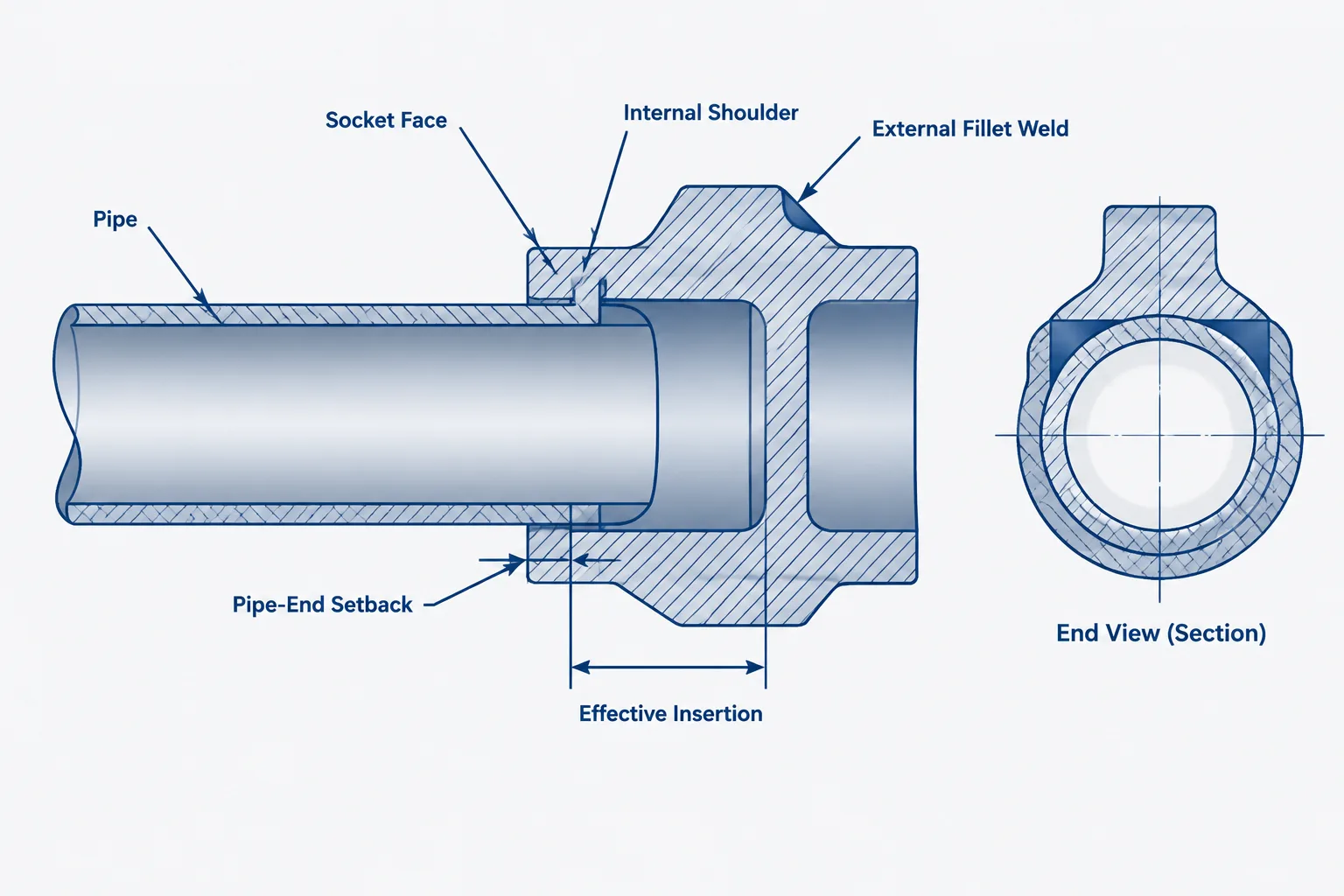
Accurate socket-weld modeling depends on geometry that is largely hidden after assembly. The CAD model, component catalog, and fabrication documents must use consistent reference planes for the socket face, installed pipe end, and internal shoulder. This guide explains how those references influence pipe cut length and why a visually correct connection can still contain a dimensional error.
Socket-weld piping can appear simple in a CAD model: place a fitting, run a pipe into it, and show a weld at the joint. The fabrication geometry is more specific. The pipe end enters a recessed socket, its installed position depends on the socket depth and required assembly gap, and the external fillet weld is separate from the internal pipe-end location.
These details affect pipe cut lengths, fitting placement, material takeoff, weld identification, and interference checks. A model that represents only the visible outside surfaces may look correct while producing an incorrect cut length or implying that the pipe is seated against the bottom of the socket.
What makes a socket-weld connection different?
A socket-weld fitting or valve end has a recessed opening that accepts the pipe. The joint generally includes four important geometric features:
- Socket face: The external end plane where the pipe enters the component.
- Socket bore: The recessed cylindrical region that receives the pipe outside diameter.
- Socket bottom or shoulder: The internal surface that limits how far the pipe could be inserted.
- External weld region: The area around the pipe and component end where the fillet weld is made.
The pipe does not simply terminate at the visible face of the fitting. It extends inside the component. That hidden engagement must be considered whenever pipe length is calculated from component locations.
Socket depth, insertion depth, and assembly gap
These terms describe related but different dimensions. Treating them as interchangeable is a common source of drafting and modeling errors.
| Term | Practical meaning | Why it matters in CAD |
|---|---|---|
| Socket depth | Distance from the socket face to the internal socket bottom or shoulder | Defines the maximum available recess within the component |
| Assembly gap | Specified separation between the inserted pipe end and the socket bottom | Changes the pipe-end location and must come from the applicable project or fabrication requirement |
| Effective insertion | Distance from the socket face to the installed pipe end | Used when calculating pipe cut length between socket-weld components |
| Weld size and profile | External weld geometry around the joint | Affects detailing and local envelope checks but does not define insertion by itself |
Conceptually, effective insertion is the socket depth less the required assembly gap. This is a geometric relationship, not a substitute for a fabrication specification. The applicable component standard, piping specification, welding procedure, fabricator practice, and project requirements must be checked before assigning either value.
A designer should not assume that every socket-weld component has the same recess geometry. Fittings, forged branches, flanges, unions, and valve bodies can use different end configurations. Nominal size and pressure-related component designation may also affect the selected item. Manufacturer data may be necessary when a generic standard does not fully define the component being modeled.
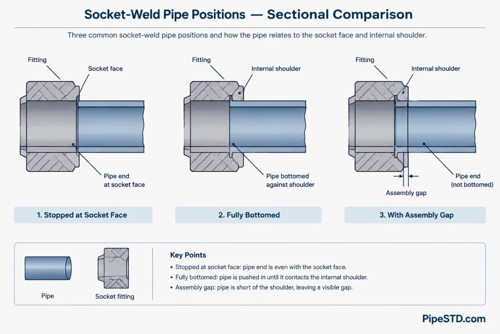
Why the pipe should not automatically be modeled against the socket bottom
A convenient modeling shortcut is to extend the pipe until it contacts the internal shoulder. That may not represent the intended assembled position. Where an assembly gap is required, a fully bottomed pipe incorrectly removes that gap.
This difference is hidden after welding, so it may not be obvious on a shaded model or general arrangement drawing. It can still affect fabrication. If cut lengths are based on full socket depth while the shop assembles the joint with a setback, the resulting spool geometry can differ from the model.
The opposite error also occurs: stopping the pipe at the socket face. That omits all engagement and makes the cut piece too short if the displayed length is used for fabrication.
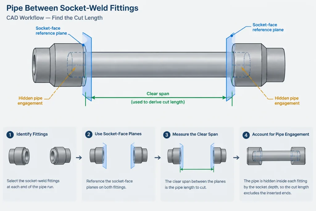
Calculating pipe cut length between socket-weld components
The most reliable method is to define clear reference planes and account for the hidden insertion at both ends. For a straight pipe piece between two opposing socket faces, the conceptual relationship is:
Pipe cut length = clear distance between socket faces + effective insertion at end one + effective insertion at end two.
This relationship is useful for understanding the joint, but the actual workflow depends on how the CAD system defines component ports and reported lengths. A port might be located at the socket face, at the pipe-end position, at the socket bottom, or at another catalog reference point. Never apply an insertion allowance twice merely because the model and a spreadsheet use different reference conventions.
A practical checking sequence
- Identify the component at each end of the pipe piece.
- Confirm where each modeled connection point is located.
- Determine whether the pipe solid extends into the socket or stops at its face.
- Verify the applicable socket depth and assembly-gap basis.
- Calculate or extract the cut length using one consistent set of reference planes.
- Compare the reported length with a simple manual geometric check.
- Document any fabrication allowance separately rather than hiding it in nominal component geometry.
For a spool containing several socket-weld joints, small reference errors can accumulate. A closed dimensional chain should therefore be checked from controlled endpoints, such as equipment connection planes, flange faces, or established tie-in coordinates.
How much socket detail belongs in the CAD model?
The appropriate level of detail depends on the model’s purpose. A coordination model may only need the external component envelope, pipe centerline, and connection location. A fabrication-oriented model may need the pipe-end position inside the socket and enough information to derive cut lengths correctly.
Simplified coordination representation
- Use the correct external fitting or valve envelope.
- Place ports at documented reference locations.
- Preserve accurate center-to-end or face relationships.
- Store the end connection as socket-weld metadata.
Fabrication-oriented representation
- Represent the pipe insertion or calculate it through catalog rules.
- Distinguish the socket face from the installed pipe-end plane.
- Provide cut lengths based on verified joint geometry.
- Identify welds using the project’s weld-numbering and documentation method.
- Show enlarged joint details when the general view cannot communicate the required assembly condition.
Modeling every internal shoulder and weld profile is not always necessary. The important point is that simplification must not corrupt the connection location or cut-length output.
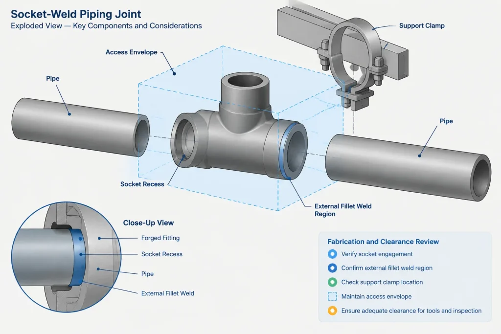
External weld geometry and clearance
The visible fillet weld occupies space around the fitting end and pipe outside diameter. In most layout models, an exact weld profile is unnecessary, but the joint should not be treated as an infinitely sharp transition when nearby objects are tightly packed.
Potential conflicts include adjacent socket-weld fittings, valve bodies, support clamps, structural steel, instrument tubing, insulation terminations, and access needed by the welder. A nominally clear solid model may still leave inadequate room for joint preparation, welding, inspection, or repair.
The weld must also not be confused with the socket face. Dimensioning to the apparent weld toe in a schematic CAD block creates an unstable reference because the final weld profile is a fabrication result rather than the primary component placement plane.
Component ports and catalog data
Socket-weld catalog components should have a clearly documented port convention. Useful data fields can include end-connection type, nominal size, component designation, socket-face location, socket depth, effective insertion rule, and source status.
A quality-control review should test more than visual appearance. Place two components at a known separation, connect them with pipe, and compare the software’s reported cut length with the expected geometric relationship. Repeat the test for different component types because a fitting socket and a valve socket may not share the same catalog construction.
Avoid creating another nominal size by scaling an existing socket-weld block. Scaling changes every feature proportionally, while real component dimensions do not necessarily change by a single scale factor. Use verified size-specific geometry or a controlled parametric definition.
Drawing and isometric documentation
General piping drawings usually do not dimension the internal socket engagement at every joint. Instead, the joint type is communicated through the piping specification, component description, weld information, and applicable fabrication details. However, the cut length shown on a spool or fabrication document must still reflect the intended assembly geometry.
If a special gap, insertion condition, or field-fit treatment applies, identify it through a controlled note or detail rather than relying on the scale of the drawing. Do not depict a generic gap and assume the shop will infer its required value.
Isometrics should also distinguish component dimensions from pipe-piece dimensions. A centerline routing dimension controls the installed arrangement, while a cut length controls the physical pipe segment. They can be related without being identical.
Common socket-weld CAD errors
- Stopping the pipe at the fitting face and omitting its hidden insertion.
- Bottoming the pipe in the socket without checking the required assembly condition.
- Adding an insertion allowance to a length that already includes it.
- Using the visible weld edge as a component reference plane.
- Assuming all fittings and valves use identical socket geometry.
- Scaling a block to represent another nominal size.
- Reporting centerline distance as pipe cut length.
- Using generic catalog geometry where manufacturer-specific dimensions control an interface.
- Showing exact-looking internal detail without recording its verified source.
A dependable workflow
Begin with the piping specification and selected component type. Obtain verified component dimensions from the applicable standard data, approved catalog source, or manufacturer information. Define what each CAD port represents, then decide whether insertion is modeled physically or handled as a cut-length rule.
After routing, validate a sample of pipe pieces manually. Check both ordinary fitting-to-fitting segments and mixed connections involving valves, unions, flanges, or branch fittings. Finally, make sure drawings, bills of material, weld records, and cut lists all use the same component identities and reference assumptions.
Socket-weld connections are compact, but their hidden geometry should not be treated casually. Clear reference planes and verified insertion rules allow a simplified CAD model to remain useful without pretending that every internal fabrication detail has been fully represented.
Managing socket-weld data through the CAD workflow
Socket-weld geometry should have a clear source and owner. Component geometry belongs in the approved catalog or library, while project-specific assembly requirements belong in controlled specifications, procedures, or fabrication notes. Keeping those inputs separate helps prevent an unverified gap or insertion assumption from becoming embedded in a reusable component.
The same distinction matters when data moves between systems. A design model may store a connection point rather than a physical pipe-end plane, while an isometric or cut-list application may apply its own engagement rule. Before trusting an automatically generated pipe length, confirm what the transferred port represents and whether either system has already accounted for insertion.
Quality-control questions for model review
- Can the reviewer identify the reference plane used by every socket-weld port?
- Is the pipe-end location modeled directly, calculated by a rule, or omitted from the solid geometry?
- Does the cut-length report use the same component identities as the visible model?
- Are special assembly or field-fit conditions communicated outside the generic catalog geometry?
- Can the source of the socket geometry be traced without relying on the appearance of the CAD object?
- Do replacement components preserve the required connection references rather than merely fitting within a similar envelope?
A useful review compares model output with an independent dimensional chain based on controlled faces or connection planes. Any unexplained difference should be resolved before the length reaches a spool drawing, cut list, or fabrication package.
Why reference-plane discipline matters
Socket-weld errors are often difficult to recognize because the fitting can remain centered on the pipe and the completed joint can look normal. The discrepancy appears in derived information: pipe-piece length, spool closure, weld location, material reporting, or connection replacement. Explicit port definitions and traceable component data make those discrepancies easier to detect before fabrication.
Frequently asked questions
Is socket depth the same as pipe insertion?
No. Socket depth describes the available recess from the socket face to the internal shoulder. The installed pipe-end position also depends on the required assembly condition, including any specified separation from that shoulder.
Should the pipe solid extend into a socket-weld fitting?
It may, but the appropriate representation depends on the model purpose and software convention. A simplified model can remain valid if its connection references and cut-length rules correctly represent the hidden engagement.
Why can a socket-weld model look correct but report the wrong cut length?
The visible outside geometry may align even when the software uses an incorrect port location or insertion rule. Errors also occur when engagement is omitted, applied twice, or based on a different component than the one shown.
Can the visible fillet weld be used as the pipe-length reference?
No. The weld profile is not the primary component placement plane. Pipe lengths should be based on documented component and connection references rather than the apparent weld edge.
What should be checked when replacing a socket-weld valve or fitting in CAD?
Verify the component identity, end-connection type, socket-face location, port convention, recess geometry, external envelope, and the rule used to establish the installed pipe end. Similar-looking components should not be assumed to be dimensionally interchangeable.
How should a special socket-weld assembly condition be documented?
Use a controlled project note, fabrication detail, or approved data field. Do not depend on an exaggerated CAD gap or a schematic weld shape to communicate the requirement.