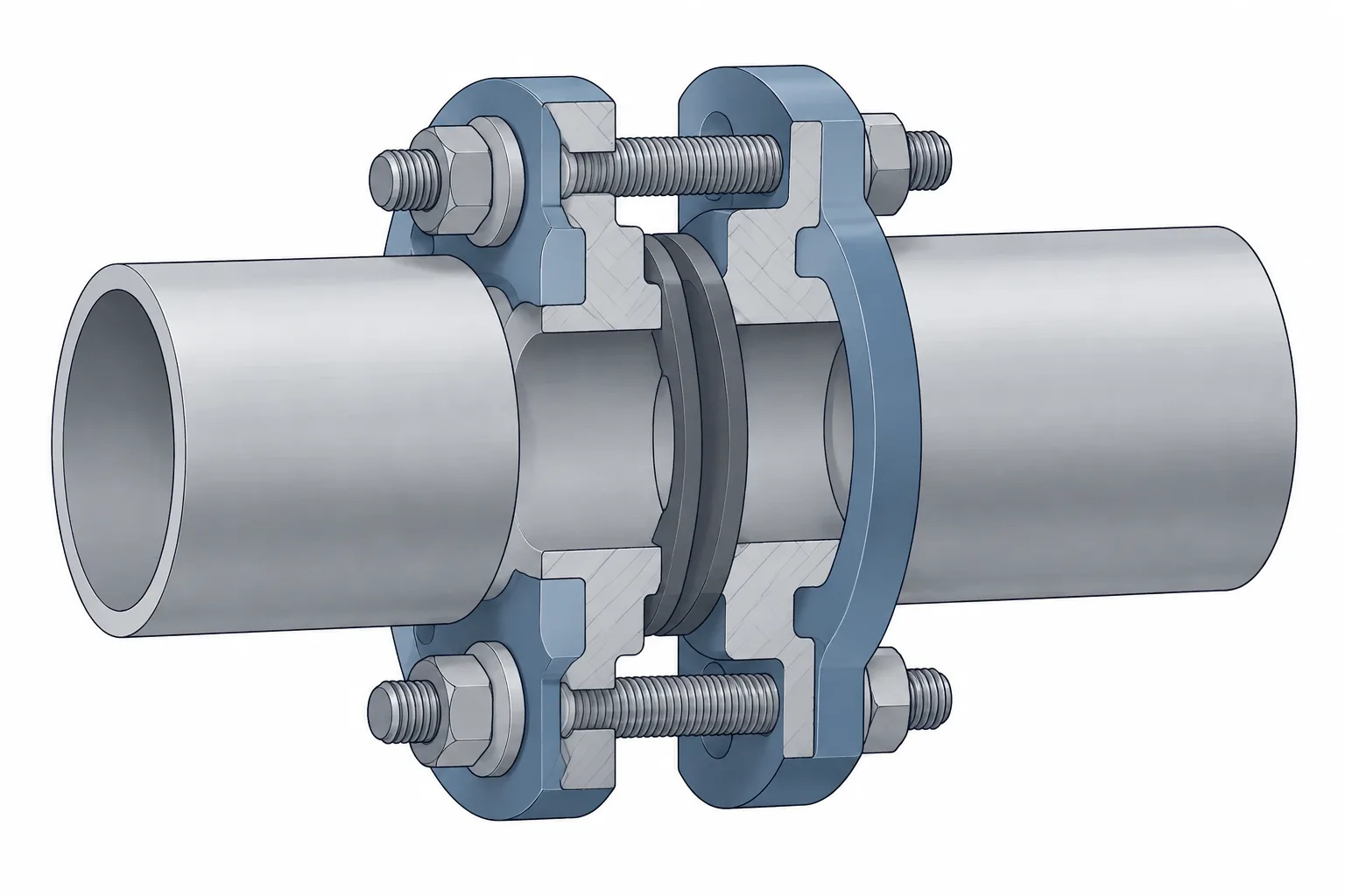
Flange bolt length in piping CAD should represent an assembly decision, not a value inferred from nominal pipe size or visual appearance. Every component crossed by the fastener—and every nut, washer, or required thread condition outside the grip—can affect the selected length.
This guide explains how to evaluate the complete flange joint stack-up, distinguish studs from machine bolts, and decide how much bolting detail belongs in a layout, coordination, or fabrication model. It also highlights where controlled project data or manufacturer information must replace generic CAD geometry.
Flange bolt length is not determined by nominal pipe size alone. It depends on the complete joint stack-up: the connected flanges or components, gasket, nuts, washers, and any additional items installed between or around the flange faces. A generic bolt that looks correct in a CAD model may therefore be too short, unnecessarily long, or incompatible with the actual assembly.
For piping designers and drafters, the important task is to distinguish between approximate layout geometry and verified bolting data. A simplified model can reserve space and show assembly intent, but fabrication and purchasing require a controlled bolt or stud length based on the specified joint configuration.
What Is a Flange Joint Stack-Up?
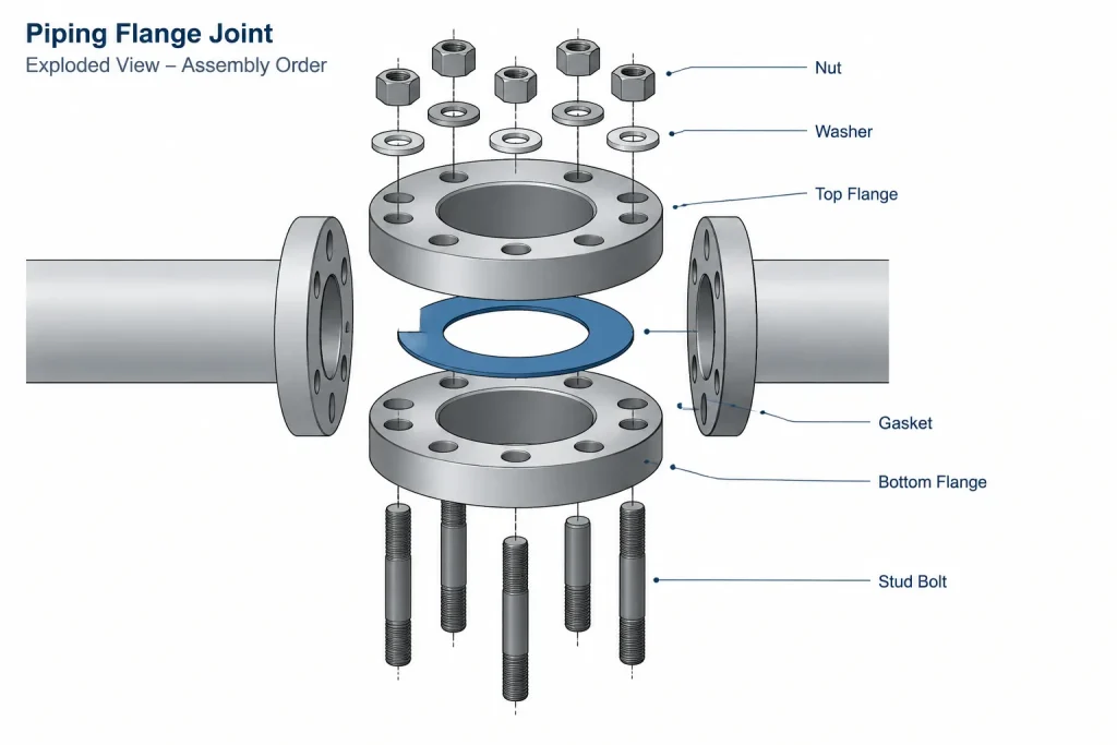
The joint stack-up is the total axial assembly through which the bolting must pass or around which the stud nuts must be fitted. In a basic two-flange joint, the stack typically includes:
- The thickness of the first flange at the bolt-hole location
- The installed gasket or sealing element between the faces
- The thickness of the second flange at the bolt-hole location
- Washers, when required by the project or bolting arrangement
- Nuts and the required thread projection or engagement
The relevant flange thickness is the material crossed by the fastener near the bolt circle. Hub length, pipe wall thickness, and overall flange projection are different dimensions and should not be substituted for the bolting grip.
The stack becomes more complicated when the joint contains a valve, spectacle blind, line blind, restriction device, insulating assembly, spacer, or other inline component. Each item can change the required fastener length.
Grip Length vs. Overall Fastener Length
Grip length is the portion of the fastener occupied by the clamped components. In a through-bolted flange joint, this generally covers the two flange sections, the gasket region, and any washers or inserted devices within the clamped stack.
Overall fastener length also accounts for the nuts and the intended thread condition beyond them. Consequently, adding the grip dimensions alone does not produce a finished stud length.
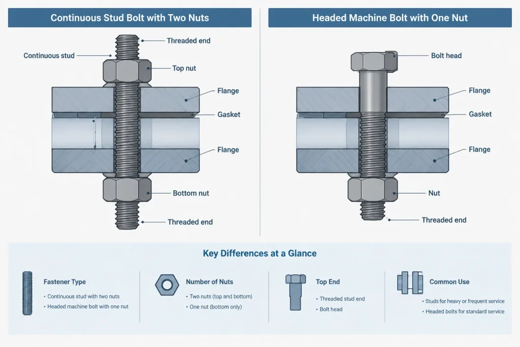
This distinction matters in CAD libraries. A component property labeled simply “bolt length” may be ambiguous unless the library defines its measurement basis. Depending on the fastener type and project convention, length may be referenced between stud ends, from under a bolt head, or by another recognized product definition. The drawing, material list, and purchasing description should use the same convention.
Stud Bolts and Machine Bolts Are Not Interchangeable Geometry
A stud bolt has threaded ends or continuous threading and normally uses a nut at each end. A machine bolt has a head at one end and usually a nut at the other. Both can clamp components, but their length definitions and space requirements differ.
| Feature | Stud bolt | Machine bolt |
|---|---|---|
| End condition | Nuts are fitted at both ends | Head at one end and typically a nut at the other |
| Length interpretation | Defined using the applicable stud convention | Generally referenced from the bearing side of the head under the applicable convention |
| Removal planning | Requires room to withdraw or manipulate the stud and nuts | Requires access for the head, nut, and bolt withdrawal |
| CAD representation | May be simplified as a threaded rod with two nuts | Should distinguish the head side from the nut side when orientation matters |
A bill of materials should not convert one type into the other merely because the nominal diameter and modeled length appear similar. Bolting material, thread series, nut type, coatings, and project requirements also need independent verification.
How Different Joint Types Change Bolt Length
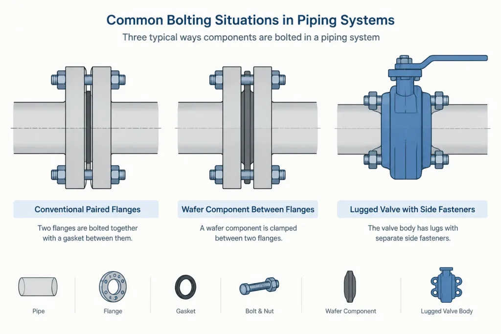
Two matching pipe flanges
A conventional flange pair may be treated as the base case, but even this joint requires the correct flange type, size, class designation, facing, and gasket arrangement. Flanges that connect to the same nominal pipe size do not necessarily have the same thickness or bolting geometry.
Flange-to-valve joints
A flanged valve end contributes its own end-flange thickness. It should not automatically be modeled as identical to a standard pipe flange. Manufacturer information may be necessary when the valve body, flange section, tapped holes, or nearby cast geometry affects bolting.
Wafer and lug-style components require particular care. A wafer component is clamped between companion flanges, while a lugged body may use separate fasteners from each side or another manufacturer-defined arrangement. Modeling every such joint as a continuous stud through the complete assembly can misrepresent both length and maintainability.
Joints with spectacle blinds, spades, or spacers
These devices add axial thickness within the flange assembly. The required bolting may also need to support more than one operating configuration. Designers should establish whether one fastener length serves all intended positions or whether a controlled bolting change is part of the operating procedure.
Flange isolation assemblies
An electrical isolation arrangement can introduce insulating sleeves, washers, backing washers, and a specialized gasket. These parts change the joint stack and may affect the usable diameter through the bolt holes. A normal flange-bolting block should not be assumed to represent the isolated joint accurately.
Orifice and specialty flange arrangements
Metering, tapped, or specialty joints may use additional hardware and project-specific assembly details. Their bolting should come from the applicable controlled design information rather than from a generic two-flange calculation.
Gasket Thickness: Nominal Data vs. Installed Condition
Gaskets have a supplied thickness and an installed condition. Compression under tightening can change the assembled separation between flange faces. The designer should use the basis required by the applicable bolting source, specification, or manufacturer rather than independently guessing a compressed dimension.
In a general arrangement model, a nominal gasket solid may be sufficient to show that a sealing element exists. In a fabrication-level assembly, the selected gasket style and controlled joint data should govern. The model should not imply that its graphical gap is a field acceptance criterion unless the project explicitly defines it that way.
Nuts, Washers, and Thread Projection
Nuts consume part of the fastener length and require adequate thread engagement. Any intended thread projection beyond the nut also contributes to the selected length. Excessive projection can create interference, while insufficient projection can indicate an incorrect fastener or assembly.
Washers are not universally included in every flange joint. When required, their quantity and location matter. A washer beneath each nut adds thickness at both ends of a stud. Specialty washer arrangements can add still more. The CAD data and material description should not silently add or remove washers without reference to the project bolting specification.
Thread projection should also be considered when checking:
- Clearance from valve bodies and operators
- Interference with adjacent pipe, steel, or equipment
- Tool access to nuts
- Removal direction for studs or bolts
- Personnel exposure around walkways and operating areas
A Practical CAD Workflow
- Identify both connected ends. Confirm the actual flange, valve, equipment nozzle, or specialty component on each side.
- Define the inserted items. Record the gasket and any blind, spacer, isolation component, wafer body, or other element in the stack.
- Confirm the bolting arrangement. Determine whether the assembly uses continuous studs, machine bolts, tapped holes, or separate fasteners from opposite sides.
- Use controlled dimensions. Obtain flange and component thicknesses from the governing dimensional source or verified manufacturer data.
- Apply the project bolting rules. Account for nuts, washers, thread convention, coatings, and required projection using approved project criteria.
- Select an available length. Do not assume that an exact mathematical result is a purchasable standard length.
- Check access and removal. Verify tool clearance and the path needed to install or extract the fastener.
- Coordinate the outputs. Keep the 3D model, detail drawing, isometric, bill of materials, and bolting schedule consistent.
What Should Be Modeled?
The appropriate bolting detail depends on the model’s purpose. Early routing models may omit individual studs and represent only the flange envelope. Coordination models may add simplified nuts and stud projections where access or clashes are important. Fabrication models may require individually controlled fasteners linked to material data.
Detailed threads are rarely necessary for general plant layout and can make models unnecessarily heavy. A simplified cylinder with recognizable nuts usually communicates the required envelope more efficiently. The metadata can carry the fastener diameter, length, material description, and assembly reference.
Where bolt length has not been verified, the component should be marked as preliminary or excluded from purchasing output. Visual realism is not evidence that the modeled fastener is correct.
Common Bolt-Length Errors
- Using one generic stud length for every flange of the same nominal pipe size
- Ignoring a gasket, blind, spacer, washer, or insulating component
- Treating a valve end flange as geometrically identical to a companion pipe flange
- Using the same logic for through-bolted and tapped-hole arrangements
- Confusing grip length with total stud length
- Scaling a fastener block without updating its controlled properties
- Allowing modeled thread projection to clash with nearby components
- Extracting preliminary fasteners into a fabrication bill of materials
Bolting Should Be Treated as Assembly Data
Flange bolting is more than a visual accessory. It is part of the joint assembly and affects procurement, installation, access, isolation details, and maintenance. Reliable CAD practice starts with the full stack-up, applies a clearly defined fastener convention, and distinguishes generic geometry from verified material data.
A good model does not merely show that bolts exist. It communicates which components are being clamped, how the fasteners are arranged, where access is required, and whether the selected length is controlled for fabrication or only representative for layout.
Managing Bolting Data Across CAD Deliverables
A reliable bolting workflow separates geometric representation from procurement status. The model may show a simplified fastener for clearance checking while its properties identify whether the length is preliminary, verified, or excluded from material output. This prevents a visually complete joint from being mistaken for an approved fabrication assembly.
Bolting records should remain associated with the specific joint rather than only with the nominal flange description. Useful assembly attributes include the connected component types, inserted items, fastener form, washer arrangement, data source, verification status, and any access constraint that influenced the orientation.
Change Control for the Joint Stack-Up
A flange connection should be reviewed whenever an item in the stack changes. Replacing a companion flange, valve, gasket arrangement, blind, spacer, or isolation component can invalidate previously selected bolting even when the line size remains unchanged.
The same review is appropriate when a model is upgraded from layout use to fabrication use. Preliminary solids can remain useful for spatial coordination, but purchasing data should be released only after the joint configuration and length convention have been checked against controlled information.
Drawing and Model Consistency
Fastener descriptions should agree across the model, isometric, detail, material list, and bolting schedule. If one deliverable identifies a stud while another describes a headed bolt, the discrepancy should be resolved rather than treated as a drafting preference.
Where detailed fasteners are omitted for model performance, the drawing can still communicate assembly intent through notes, joint identifiers, or controlled metadata. The objective is traceability: reviewers should be able to determine what the modeled geometry represents and whether it is authorized for fabrication.
Final Review Questions
- Are the actual connected ends identified rather than assumed from nominal pipe size?
- Does the stack include the gasket and every inserted component?
- Is the fastener arrangement through-bolted, tapped, or split between opposite sides?
- Are nuts and required washers represented in the length basis?
- Is the length convention clear for the selected fastener type?
- Has access for tightening, installation, and removal been checked?
- Is the modeled bolting clearly marked as preliminary or verified?
- Do the model properties and material outputs describe the same assembly?
Frequently Asked Questions
Can flange bolt length be selected from nominal pipe size alone?
No. Nominal pipe size does not define the complete clamped assembly. Flange or component thicknesses, gasket arrangement, inserted devices, nuts, washers, and thread requirements must all be considered.
Is grip length the same as stud length?
No. Grip length describes the clamped portion of the joint. Overall stud length must also reflect the applicable nut and thread conditions under the selected fastener convention.
Should a valve flange be treated like a matching pipe flange?
Not automatically. The valve end may have different geometry, tapped holes, or nearby body features. Verified component or manufacturer information should govern when those details affect the bolting.
Do all flange joints require washers?
No. Washer use depends on the specified bolting arrangement and project requirements. When washers are required, their quantity and location must be included in the stack-up.
Must detailed threads be modeled in CAD?
Usually not for general layout. Simplified fastener geometry can communicate the required envelope while controlled properties carry the assembly information. More detail may be appropriate when fabrication or a specific interference check requires it.
When should modeled bolting be excluded from a material list?
Bolting should be excluded or clearly marked preliminary when its joint configuration, length basis, or material description has not been verified for purchasing.
What changes should trigger another bolt-length review?
Review the bolting whenever a connected flange, valve, gasket, blind, spacer, isolation component, washer arrangement, or fastener type changes.