Pipe nipples in CAD require more definition than their simple shape suggests. A useful model must distinguish the component’s physical length from its assembled exposure while preserving the correct end conditions, orientation, and material-reporting behavior.
This reference explains how those distinctions affect component placement, threaded connections, purchasing descriptions, fabrication documents, and material takeoffs. It also identifies where a project convention or verified supplier information is more reliable than assumed geometry.
A pipe nipple is a short piece of pipe used to connect fittings, valves, instruments, equipment, or other piping components. It may look simple in a model or drawing, but its length and end configuration can affect assembly, purchasing, clearance, and material reporting. Problems occur when a generic cylinder is treated as interchangeable with a specified stock nipple or when its modeled length is mistaken for the visible length after threaded assembly.
For CAD work, the essential questions are: What do the stated length and reference points represent? Are the ends threaded, plain, beveled, socket-weld, or different at each end? Is the item purchased as a finished component or fabricated from pipe? The answers determine how it should be modeled, dimensioned, and listed.
What Is a Pipe Nipple?
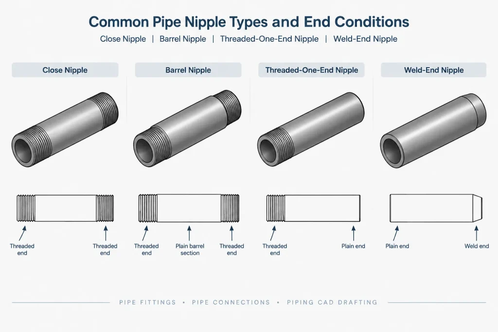
In common piping usage, a nipple is a relatively short tubular component with a prepared connection at one or both ends. Male pipe threads on both ends are common, but the term is also used for pieces with one threaded end and one welding end, or for short weld-end pieces supplied as components.
Terminology is not perfectly uniform across industries and suppliers. A project specification or catalog may distinguish several nipple forms, while another source may group them under one general description. Therefore, the word nipple by itself is not enough for purchasing or fabrication. Size, wall designation, material, length, end preparation, and any applicable component description still need to be established.
A pipe nipple should also not be confused with a swage nipple. A swage nipple changes size through a tapered body, while an ordinary pipe nipple generally retains one nominal size along its length.
Common Nipple Descriptions
| Description | Typical meaning | CAD and documentation concern |
|---|---|---|
| Threaded both ends | A straight piece with external threads at each end | Overall length is not the same as exposed installed length |
| Close nipple | A very short nipple with threads occupying most or all of the available body | Supplier geometry and wrenching provisions must be verified |
| Barrel nipple | A threaded nipple with a visible unthreaded section between the end threads | Do not infer the unthreaded length from a generic symbol |
| Threaded one end | One male-threaded end with another end prepared differently or left plain | End orientation must be identified |
| Weld-end nipple | A short component prepared for welding at one or both ends | Weld preparation and component length require specification control |
Names such as close, short, long, or barrel are useful descriptions, but they should not replace verified dimensional and purchasing data. A designer should not assign an assumed length merely because a familiar trade term appears in a line specification.
Overall Length vs. Installed Exposure
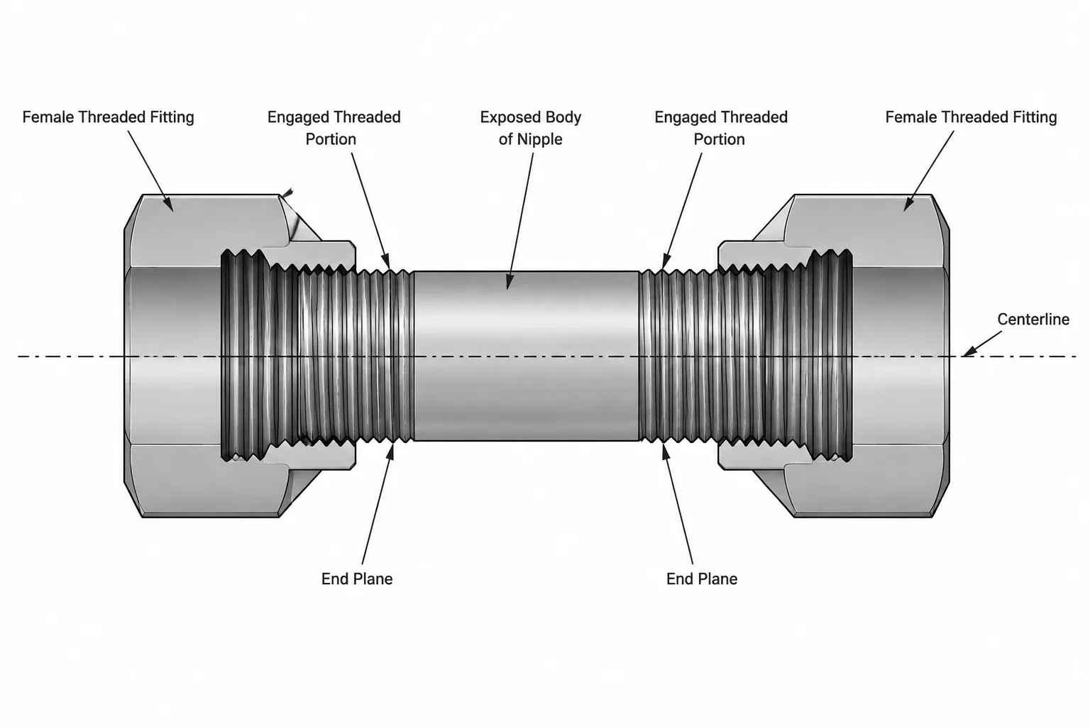
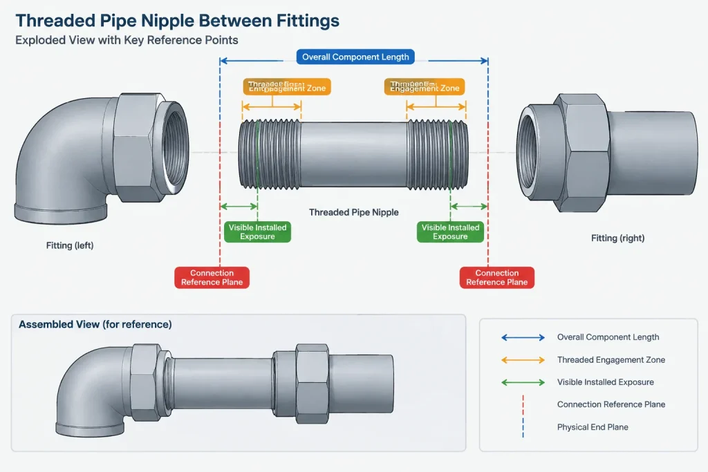
The stated length of a straight nipple is commonly an end-to-end physical length before assembly. When the nipple is threaded into fittings, portions of both ends enter the adjoining female threads. The visible or exposed distance between the connected components is therefore less than the nipple’s overall length.
This distinction matters when positioning elbows, couplings, valves, instrument root connections, or equipment accessories. If a CAD model places each fitting at the nipple’s physical end plane without representing engagement, the resulting assembly may be too long. If the designer instead forces fitting faces together using an arbitrary thread overlap, the model may imply a level of field predictability that threaded makeup does not provide.
Threaded makeup depends on the thread system, component tolerances, coating, sealant, assembly practice, and required leak tightness. It should not be treated as an unrestricted sliding adjustment. The project should use an approved modeling convention or verified manufacturer information where installed dimensions are critical.
Useful Reference Planes
A nipple model may need more than one type of reference:
- Physical end plane: the actual end of the unassembled component.
- Nominal connection plane: a project-defined placement point used to connect compatible CAD objects.
- Fitting face or body reference: a visible surface on the adjoining component used for layout dimensions.
- Assembly centerline: the common axis used to align the nipple and connected components.
These references should not be silently treated as equivalent. A clear component origin and insertion convention helps prevent cumulative errors in threaded assemblies.
End Connections Must Be Explicit
A material description should state the end condition rather than relying on the component name. For a mixed-end nipple, orientation can also matter. A threaded end connected to a valve and a beveled end connected to pipe cannot be reversed without changing the intended joint arrangement.
Useful end descriptions may include threaded, plain, beveled, socket-weld preparation, or another project-defined condition. The drawing does not need to show a detailed thread helix to communicate this information. Connection metadata, end symbols, notes, and the bill of materials are normally more reliable than highly detailed graphics.
Where threads are visually represented, a simplified drafting convention is generally preferable. Modeling actual helical thread geometry increases file size and can make drawings difficult to read without improving layout accuracy. Detailed thread form belongs in manufacturing-level documentation when it is genuinely required.
Purchased Nipple or Fabricated Pipe Piece?
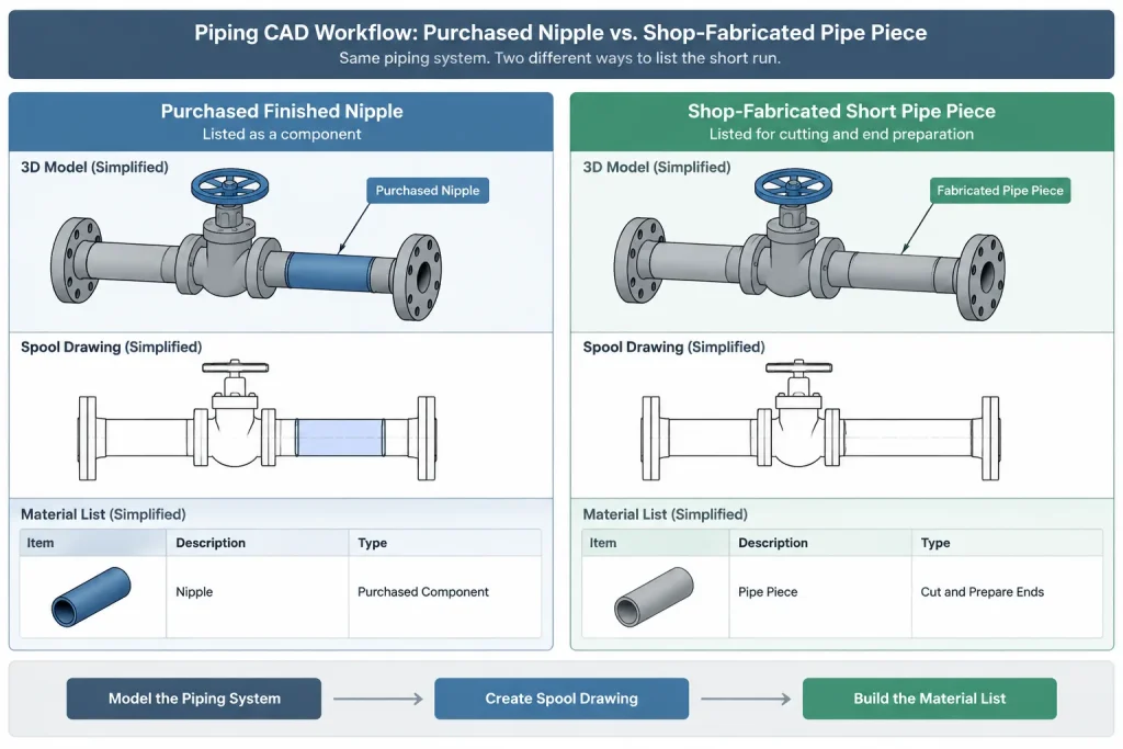
A key documentation decision is whether the nipple is a purchased finished item or a piece fabricated from project pipe. Two objects with similar external geometry may have different procurement, inspection, traceability, and costing requirements.
- A purchased nipple may be ordered by a defined size, material, wall designation, end configuration, and nominal overall length.
- A fabricated piece may be cut from pipe and have its ends threaded, beveled, or otherwise prepared by the fabricator.
- A special nipple may require a controlled drawing or item description because a generic catalog label does not fully define it.
The CAD model should not decide this classification solely from component length. The piping material specification, fabrication strategy, and procurement rules should control how the item appears in the material takeoff.
Modeling Pipe Nipples at Different Levels of Detail
Schematic and P&ID Use
A P&ID usually does not need each nipple represented as a separate physical item. Its purpose is to communicate process function, isolation, instrumentation, and connectivity. Nipples may become relevant only when they are part of a specifically identified assembly or connection detail.
General 3D Layout
For layout, a nipple can often be represented by its correct outside envelope, overall length, connection types, and placement references. Thread reliefs and small edge details may be omitted unless they influence access or interference.
Fabrication or Assembly Detail
A fabrication-level representation may need to distinguish purchased overall length, end preparation, installed relationship, and adjacent fitting references. Even at this level, modeled thread engagement should be treated as a documented convention rather than an exact prediction of field makeup.
Material Takeoff and Cut-Length Control
A purchased nipple should normally appear as a component item rather than being counted as an ordinary length of straight pipe. Conversely, a shop-fabricated piece may need to appear in a cut list with its raw cut length and required end operations.
Before issuing an MTO or spool drawing, check the following:
- Is the nipple identified as purchased or fabricated?
- Does the reported length mean physical overall length, raw cut length, or installed face-to-face distance?
- Are both end connections defined?
- Are nominal size, material, and wall designation inherited from the correct piping specification?
- Does a mixed-end item have a controlled orientation?
- Is a trade description such as close nipple supported by verified item data?
- Has the model avoided double-counting the nipple as both a component and straight pipe?
Common CAD Errors
- Scaling one nipple block for another size: scaling changes every feature proportionally and does not create verified size-specific geometry.
- Using overall length as visible gap: this ignores the portions entering threaded fittings.
- Assuming fixed thread penetration: actual assembly position is affected by several variables and should follow the project convention.
- Leaving mixed ends unidentified: visually similar ends can represent different joint types.
- Calling every short pipe piece a nipple: this can obscure whether the item is purchased, cut from pipe, or part of another assembly.
- Adding excessive thread geometry: detailed helices can burden the model without improving design control.
A Practical CAD Workflow
- Read the applicable piping material specification and determine how the nipple is classified.
- Select the nominal size, material, wall designation, and end configuration from controlled data.
- Confirm whether length is a purchasing attribute, a fabricated cut length, or a derived assembly dimension.
- Place the component using its centerline and documented connection references.
- Apply the project’s threaded-engagement convention without implying exact field makeup.
- Check nearby fitting bodies, valve operators, wrench access, and instrument clearances.
- Verify that the drawing and MTO report the item consistently.
- Use supplier-specific dimensions when the installed envelope is critical.
Key Takeaway
A pipe nipple is more than a short cylinder between two fittings. Its overall length, installed exposure, end preparations, procurement classification, and connection references describe different aspects of the assembly. A reliable CAD model keeps those concepts separate, uses controlled component data, and clearly identifies which dimensions are physical, derived, or based on a project modeling convention.
Using Nipple Data Across CAD Deliverables
The same nipple may be represented differently across a piping model, assembly drawing, spool document, and material takeoff. That variation is acceptable when every deliverable refers to the same controlled component definition. Problems begin when graphical simplification changes the intended length basis, end preparation, or procurement classification.
A practical information hierarchy starts with the piping material specification and approved component data. The CAD object then carries the connection behavior and reporting attributes required by the project. Drawing notes and dimensions communicate the installation or fabrication intent without overriding the controlled item description.
Model Review Priorities
- Geometry: Confirm that the modeled envelope represents the selected component rather than a scaled generic cylinder.
- Connections: Check that each end has the intended connection type and that mixed ends are oriented correctly.
- References: Identify whether placement uses physical ends, nominal connection planes, fitting faces, or another documented project reference.
- Reporting: Verify that the item appears in the correct material takeoff or cut list and is not counted twice.
- Assembly intent: Make clear that modeled threaded engagement is a design convention unless verified assembly information controls the installed relationship.
Coordination at Interfaces
Nipple-related discrepancies often appear at valves, instruments, fittings, and equipment connections because several component references meet in a small area. Reviewing the complete connection assembly is more dependable than checking the nipple by itself. The reviewer should compare model placement, item description, adjacent component references, and the dimension shown on the issued drawing.
If clearance depends on the final assembled position, the design team should identify the controlling reference and obtain verified component information. A visually plausible CAD connection should not be treated as proof of exact field makeup.
Pipe Nipple CAD Questions
Should nipple length be used as the gap between connected fittings?
Not automatically. The physical overall length and the exposed installed distance represent different conditions when part of the nipple enters adjoining threaded components. The model should follow the project’s documented connection convention.
Does a CAD model need detailed helical threads?
Usually not for piping layout. Simplified thread graphics, connection metadata, and clear end descriptions generally communicate the design intent more effectively. Detailed thread form should be reserved for documentation that genuinely requires manufacturing-level geometry.
Can a close nipple be created by shortening a generic nipple model?
That approach does not establish verified component geometry. A close nipple description can involve supplier-specific body and thread relationships, so controlled item data should govern the model and purchasing description.
How should a nipple with different end connections be modeled?
Each end should have its own connection definition, and the object should retain a controlled orientation. The drawing, model metadata, and material description should agree on which end connects to each adjacent component.
Should a nipple appear as pipe or as a component in the material takeoff?
That depends on whether it is purchased as a finished item or fabricated from project pipe. The piping specification, procurement strategy, and fabrication requirements should determine its reporting classification.
Can threaded makeup be used as a field adjustment allowance?
It should not be treated as unrestricted adjustment. Assembly position depends on the thread system, tolerances, coatings, sealant, and installation practice. Critical installed dimensions require an approved convention or verified component information.