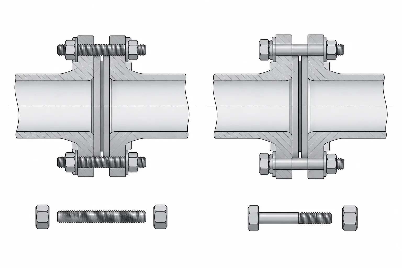
Identifying stud bolts vs. machine bolts is more than a terminology exercise. The fastener form affects how a flanged joint is assembled, which side requires insertion clearance, how the installed envelope should appear in CAD, and what information belongs in the bill of materials.
This guide explains the practical differences without treating generic model geometry as verified purchasing data. Final fastener selection and documentation must remain consistent with the governing piping specification, flange or equipment requirements, and approved project information.
Stud bolts and machine bolts can both clamp a flanged joint, but they are not interchangeable descriptions. They have different physical forms, length conventions, assembly methods, and procurement requirements. Treating every flange fastener as a generic “bolt” may be acceptable in a simplified layout model, but it can create ambiguity in bills of material, fabrication drawings, maintenance planning, and equipment interfaces.
The correct fastener arrangement depends on the flange design, joint configuration, applicable standard, piping specification, equipment requirements, materials, and project practices. CAD geometry should therefore communicate the required envelope without implying unverified fastener details.
What Is a Stud Bolt?
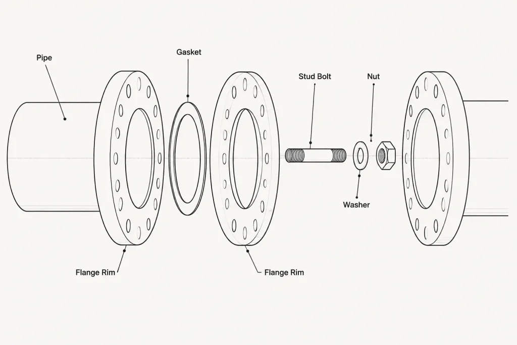
A stud bolt is a threaded rod used with a nut at each end. In flanged piping, the stud passes through aligned holes in the two flange rims and clamps the joint when the nuts are tightened. Piping stud bolts are commonly threaded along most or all of their length, although the exact thread form and end configuration must be taken from the applicable specification.
Because a stud has no permanent bolt head, either end may often be inserted through the joint during assembly. This can be useful when piping geometry or nearby structures restrict access from one side. Both nuts still require tool access for installation, tightening, and future removal.
A stud bolt assembly may include:
- One stud of the specified diameter, thread, material, and length
- Two compatible nuts
- Washers when required by the joint design or project specification
- Coatings, plating, or other surface treatment when specified
- Identification and traceability information required by procurement documents
The word stud alone is not enough for purchasing. The material, thread, length, nut requirements, coating, and quantity must be defined through controlled project data.
What Is a Machine Bolt?
A machine bolt has an integral head at one end and normally uses one nut at the other. The head prevents the fastener from passing completely through the flange hole and provides a reaction surface while the nut is tightened.
Machine bolts may be used in some piping flange assemblies, lower-pressure utility systems, specialty joints, proprietary equipment connections, or project-specific applications. Their use should not be assumed merely because a drawing symbol resembles a headed bolt. The piping specification, flange requirements, and equipment documentation determine whether a headed fastener is permitted.
A machine-bolt assembly typically requires access for inserting the bolt from the head side and access for installing and tightening the nut from the opposite side. The head also has a defined shape and envelope that may matter near walls, structural members, valve bodies, or equipment casings.
Stud Bolts vs. Machine Bolts at a Glance
| Feature | Stud bolt | Machine bolt |
|---|---|---|
| Basic form | Threaded member without an integral head | Fastener with an integral head |
| Typical nut arrangement | One nut at each end | One nut opposite the head |
| Insertion | May often be inserted from either side, subject to access | Must be inserted in the required head-to-nut direction |
| Length reference | Generally described by overall end-to-end length | Commonly measured from the bearing surface under the head to the end |
| CAD envelope | Nuts and stud projection occur on both sides | Bolt head on one side and nut with projection on the other |
| BOM description | Stud and nuts must be accounted for | Bolt and nut must be accounted for |
Length terminology and product conventions should always be confirmed in the governing purchasing specification. A nominally equal stated length does not necessarily create the same installed projection for the two fastener types.
Why Fastener Length Is a Joint Stack-Up
Fastener length cannot be selected reliably from flange thickness alone. It is derived from the complete clamped assembly and the required engagement or projection.
The joint stack-up can include:
- Both flange thicknesses at the bolt locations
- The compressed or specified gasket contribution
- Nuts and any required washers
- Raised faces, ring-joint geometry, or other facing arrangements as applicable
- Additional components such as a spectacle blind, spacer, or temporary test item
- Required thread engagement and permitted projection beyond the nut
Changing a gasket arrangement or inserting a line blind can therefore affect required fastener length even when the flange size and pressure class remain unchanged. CAD and material-control workflows need a way to distinguish permanent joint hardware from temporary or alternate operating configurations.
Assembly Direction and Access
A model may show that fasteners physically fit through the flange holes while failing to show whether they can be installed. Machine bolts require a clear insertion path at least on the head side. Studs reduce the importance of head direction, but they still need axial space for insertion and radial space around both nuts for tools.
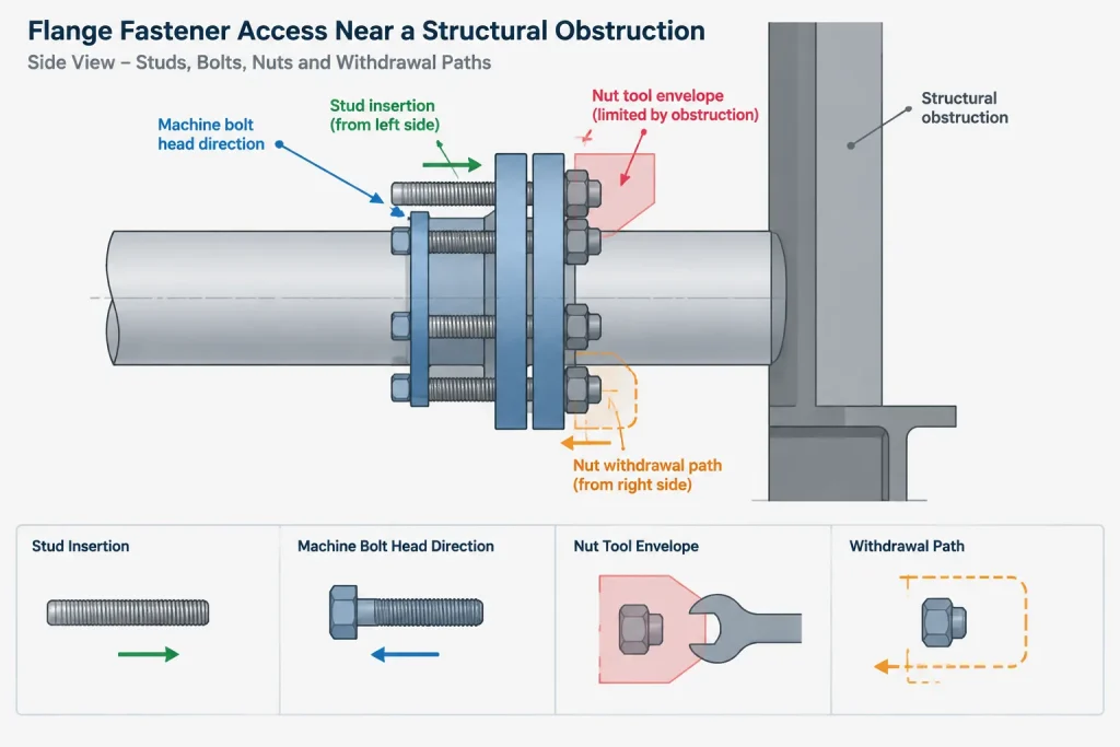
Design reviews should consider:
- Nearby pipe, structural steel, handrails, walls, and equipment
- Valve bodies, bonnets, gear operators, and actuator brackets
- Whether a long fastener can be withdrawn without moving another component
- Wrench or powered-tool access around nuts and bolt heads
- Access after insulation, guards, platforms, or removable covers are installed
- Whether maintenance requires complete fastener removal or only loosening
For a machine-bolted joint, reversing the bolt direction may solve one obstruction while creating another. The selected direction should be shown when it affects installation or maintenance; otherwise, the model should not imply that an arbitrary graphic orientation is mandatory.
Special Case: Tapped Holes at Equipment Interfaces
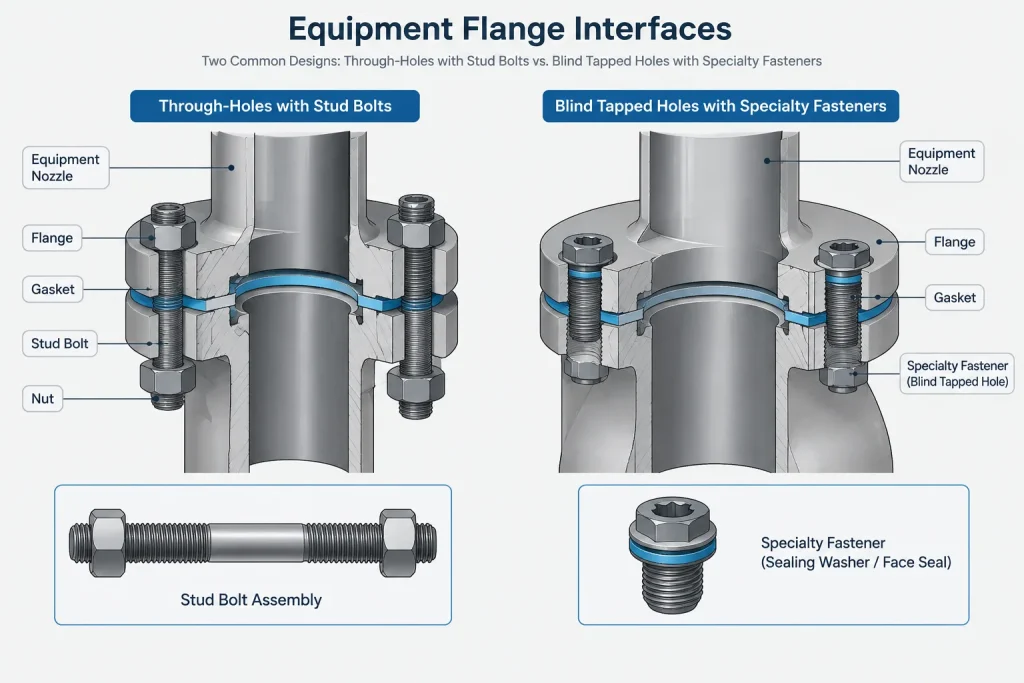
Not every flanged-looking connection uses through-holes with nuts on both sides. Pumps, valves, machinery casings, and proprietary equipment may include tapped holes where a fastener threads directly into the equipment. Blind tapped holes require particular attention because available thread depth and maximum insertion are controlled by the equipment design.
A through-stud arrangement should not be substituted for a tapped-hole connection in CAD without verification. Likewise, generic flange bolting data may not apply at an equipment interface. Vendor drawings and approved interface information should control the hole type, thread, fastener form, engagement, and permitted projection.
Tap-end studs and other specialty fasteners may also use different threads or engagement requirements at opposite ends. They should be identified as specific components rather than modeled or purchased as ordinary flange studs.
How Much Fastener Geometry Should CAD Show?
The appropriate level of detail depends on the purpose of the model. A conceptual layout may represent the bolting region as a simple clearance envelope. A coordinated plant model may show individual studs or bolt heads where access and clashes matter. A fabrication or assembly model may need more explicit hardware geometry and controlled item data.
Simplified representation
For general arrangement work, model enough geometry to reserve space around the flange and identify potential obstructions. Avoid modeling cosmetic thread helices; they add complexity without improving most piping coordination tasks.
Detailed representation
Where removal or tool access is critical, show the head or nut envelopes, expected projection, and withdrawal direction. Detailed geometry should remain connected to verified component data rather than being created by visually scaling a generic fastener.
Equipment connections
Use vendor-controlled interface geometry when fasteners enter tapped holes, pass through a casing flange, or have restricted insertion depth. Mark unresolved information as a hold instead of assuming that a standard piping flange arrangement applies.
BOM and Specification Data to Control
A useful bolting record separates physical geometry from procurement data. Depending on project practice, the following fields may be required:
- Fastener type: stud bolt, machine bolt, tap-end stud, or other defined type
- Diameter and thread designation
- Length and the applicable length convention
- Fastener material or controlled material designation
- Nut type, material, and quantity
- Washer type and quantity when required
- Coating or surface treatment
- Quantity per joint and total project quantity
- Associated piping class, joint type, or equipment connection
A BOM should also make clear whether nuts are included with the stud item or listed separately. Otherwise, counting the correct number of studs can still produce an incomplete purchase order.
Practical CAD Review Checklist
- Confirm whether the joint requires studs, headed bolts, or specialty fasteners.
- Verify that bolt-hole quantity and arrangement come from controlled flange or equipment data.
- Build length from the actual joint stack-up rather than flange thickness alone.
- Check insertion, tightening, and withdrawal space.
- Account for blinds, spacers, washers, insulation, and other additions to the joint.
- Do not apply generic through-bolting to blind tapped equipment holes.
- Ensure the model item, drawing callout, and BOM use consistent terminology.
- Flag unverified vendor connections instead of assigning assumed fastener dimensions.
The Key Documentation Principle
“Bolting” is a functional category, not a complete component description. Stud bolts and machine bolts may serve the same clamping purpose, but their geometry, nut arrangement, insertion path, and length definitions differ. A reliable piping workflow identifies the actual fastener type, models the access envelope appropriate to the project stage, and keeps procurement details tied to the governing joint data.
Translating Joint Requirements into CAD and Drawings
A reliable documentation workflow separates the joint’s physical envelope from its procurement identity. Simplified geometry may be adequate for layout coordination, but the associated item data must still identify whether the connection uses a stud, a headed bolt, or a specialty fastener.
Geometry and access
Model the space needed for the applicable head, nuts, projection, tool access, insertion, and withdrawal. The representation should help reviewers find clashes without suggesting that visually estimated geometry is approved for fabrication or purchasing.
Component identity
Use consistent terminology in the model properties, drawing notes, material takeoff, and BOM. A generic bolting label can conceal important differences in nut quantity, length convention, coating, thread designation, and assembly direction.
Verification status
Unresolved flange or equipment interfaces should be clearly identified as requiring confirmation. This is especially important where tapped holes, restricted engagement, casing geometry, or vendor-controlled fasteners replace a conventional through-bolted arrangement.
Questions for a Model-to-Drawing Review
- Does the drawing name the actual fastener type rather than using bolt as a universal description?
- Does the modeled envelope represent the head-and-nut or nut-at-both-ends arrangement correctly?
- Can the fastener be inserted, tightened, loosened, and withdrawn in the installed location?
- Are additional joint components reflected in the stack-up and fastener review?
- Do the model item, drawing callout, and BOM refer to the same controlled component?
- Are equipment-interface details based on approved information rather than a generic flange assumption?
Frequently Asked Questions
Can a generic bolting symbol represent either fastener type?
A generic symbol may be acceptable in an early or simplified layout when detailed hardware is outside the model scope. The drawing notes, model data, and BOM should not leave the actual fastener type ambiguous when it affects assembly or procurement.
Do a stud bolt and machine bolt with the same stated length occupy the same installed space?
Not necessarily. Their length references and end arrangements differ, so installed projection must be evaluated from the applicable convention and complete joint stack-up.
Does a stud bolt eliminate access concerns?
No. A stud avoids the fixed head orientation of a machine bolt, but installation still requires axial insertion space and access to the nuts on both sides. Tool clearance and future withdrawal also remain important.
Should washers be included automatically in a flange model or BOM?
No. Washers should be included only when required by the joint design, piping specification, equipment documentation, or project practice. Their presence also affects the joint stack-up.
How should a tapped equipment connection be documented?
Use approved equipment information to define the hole type, thread, fastener form, engagement, and permitted insertion. Do not convert the interface into a generic through-bolted flange connection without verification.
Should CAD models include detailed thread geometry?
Usually, the important information is the fastener envelope and controlled thread designation rather than a cosmetic helical thread. More detailed geometry may be appropriate when it supports a specific assembly or interface review.