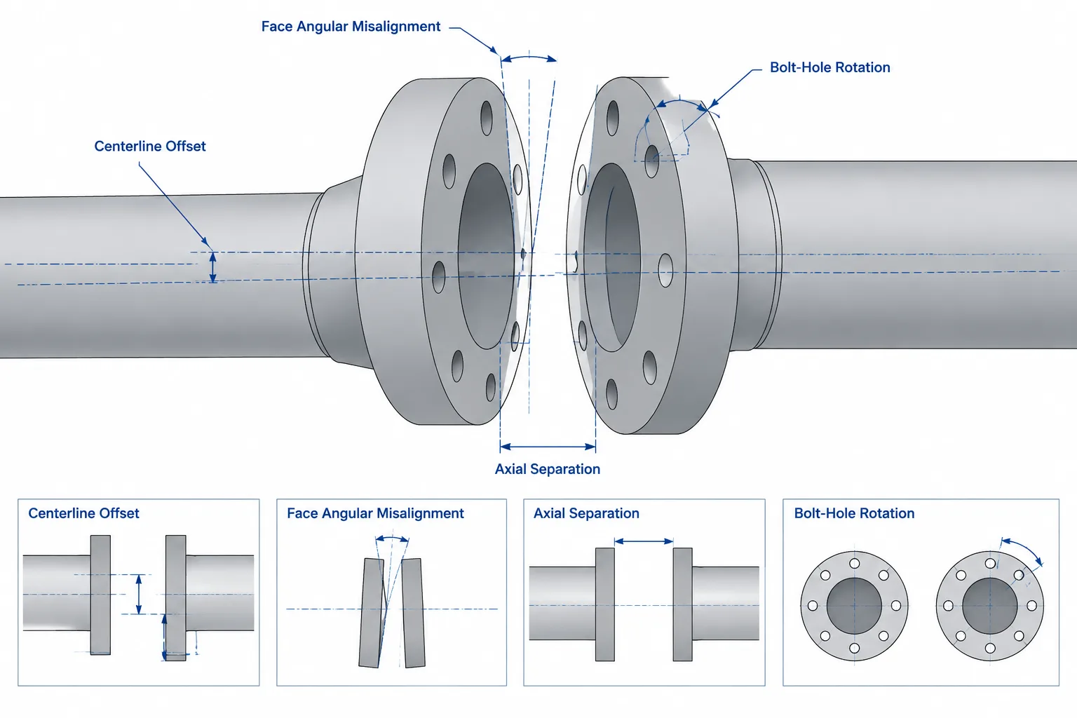
Flange alignment in piping CAD requires more than confirming that two connection points meet. A reliable review separates centerline position, face orientation, axial fit-up, and bolt-hole clocking so that each mismatch can be identified and corrected at its source.
This guide explains how those conditions appear in a model, why simplified geometry can conceal them, and what designers should verify before treating a flanged interface as coordinated.
A piping model can show two flanges connected perfectly while the fabricated parts remain difficult—or impossible—to assemble without correction. Flange alignment is not a single condition. It includes the position of the flange centers, the orientation of the sealing faces, the axial distance between faces, and the rotational relationship of the bolt holes.
Understanding these separate conditions helps designers diagnose fit-up problems instead of treating every mismatch as a generic alignment error. It also improves model reviews, spool dimensioning, equipment coordination, and field-verification planning.
What flange alignment means
Two mating flanges must form a joint in which their connecting features are compatible. In idealized CAD geometry, the flange centerlines are coincident, the faces are parallel, the bolt patterns are correctly clocked, and the intended joint stack-up fits between the face planes.
Real assemblies are influenced by pipe tolerances, fitting geometry, welding distortion, support elevations, equipment position, fabrication sequence, and field conditions. The model therefore represents the intended geometry, not a guarantee of as-built fit.
Flange alignment is best reviewed as several independent checks:
- Lateral or centerline offset: The flange axes are parallel but do not share the same centerline.
- Angular misalignment: The flange axes are not parallel, so the sealing faces are not properly aligned.
- Axial gap or interference: The distance between the flange faces does not match the intended joint arrangement.
- Rotational misalignment: The bolt-hole patterns are clocked differently and cannot accept the intended bolting arrangement.
- Combined misalignment: Two or more of these conditions occur together.
Four alignment conditions to check in CAD
1. Lateral offset
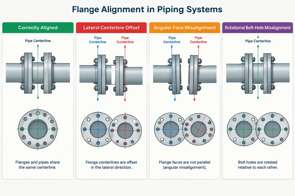
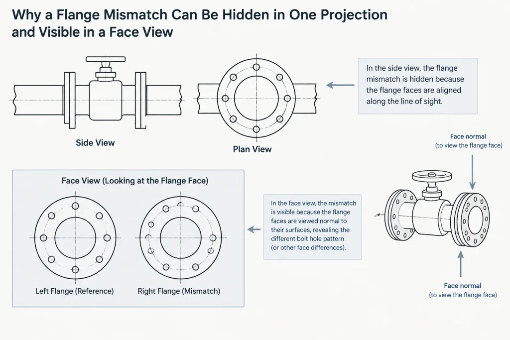
Lateral offset occurs when mating flange centers are displaced across the face plane. The faces may still be parallel, which can make the problem difficult to recognize in an elevation or side view. A view looking normal to the flange faces usually reveals it more clearly.
This condition can result from an incorrect pipe centerline, a nozzle location discrepancy, an uncoordinated support elevation, or a fitting takeoff error. Moving only the flange symbol is not a valid correction if the connected pipe and fittings remain on the original centerline. The entire connected geometry and its controlling dimensions must be reviewed.
2. Angular misalignment
Angular misalignment exists when one flange face is tilted relative to the other. The center points might appear to coincide, but the face normals point in different directions. If the joint is pulled together by tightening bolts, the connected pipe, equipment nozzle, or flange may be subjected to unintended loading.
In a 3D model, face-normal vectors provide a more dependable check than visual inspection alone. In 2D drawings, angular error can be hidden by the selected projection. Orthographic views from more than one direction may be needed to expose it.
3. Axial gap or interference
The axial relationship is measured along the connection axis between the relevant face planes. A gap may represent the intended joint stack-up, an omitted component, an incorrect face-to-face dimension, or simply incomplete model detail. Interference means the modeled parts occupy overlapping axial space.
The correct model treatment depends on project convention. Some piping models represent the gasket or other joint elements explicitly, while others use connection rules and data without showing every thin component. Reviewers must understand that convention before identifying a gap as an error.
4. Bolt-hole rotation
Two flanges can be concentric, parallel, and correctly spaced while still having incompatible bolt-hole orientation. This rotational mismatch is often called incorrect clocking.
A simplified flange represented only by outside and bore circles cannot support a visual clocking check. The component must either include bolt-hole geometry or carry a reliable orientation reference. This is especially important at equipment nozzles, valve connections, special flanges, and interfaces supplied by different parties.
Alignment terminology at a glance
| Condition | What differs | Useful CAD check | Possible source |
|---|---|---|---|
| Lateral offset | Axis location | Compare connection centers in the face plane | Centerline, support, or nozzle-position discrepancy |
| Angular misalignment | Axis direction and face orientation | Compare face normals or axis vectors | Rotation error, weld distortion, or sloped routing |
| Axial mismatch | Face-plane separation | Measure along the connection axis | Wrong component length, omitted joint element, or interface error |
| Rotational misalignment | Bolt-pattern clocking | Compare hole centers or orientation references | Incorrect component rotation or unverified nozzle data |
Why perfect centerlines are not enough
Centerline-based modeling is efficient for routing, but a centerline connection proves only part of the interface. It does not automatically prove that the faces are parallel, the bolt patterns align, or the axial stack-up is correct.
This distinction becomes important where generic library components meet vendor-supplied equipment. A nozzle may have the expected nominal size and flange type while its projection, orientation, facing, or bolt-hole clocking remains unverified. Connecting a pipe centerline to the nozzle center point can make the model appear complete before the actual interface has been confirmed.
A practical CAD review workflow
Confirm the governing interface
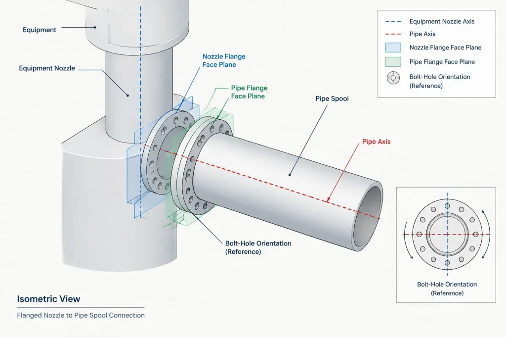
Identify which side controls the connection. An equipment nozzle, existing flange, skid boundary, or packaged-unit connection may be fixed, while the connecting pipe is adjusted to suit. Avoid moving a controlled interface merely to eliminate a model warning.
Check component identity and end type
Verify that the modeled flange or flanged component represents the intended nominal size, pressure class, facing arrangement, and connection type. Geometric alignment does not establish specification compatibility.
Compare connection origins and axes
Review the coordinates of the connection points, then compare their axis directions. Opposing connection ports generally need compatible axes directed toward the joint. A port that is located correctly but points in the wrong direction may indicate a rotated or incorrectly defined component.
Review the face planes
Measure the separation of the actual mating face references rather than relying on component insertion points. Insertion origins vary among libraries and may be placed at a face, flange center, hub end, or component center.
Verify bolt-pattern orientation
Use modeled holes, a bolt-circle reference, or a documented orientation parameter. Do not infer clocking from the outline of a circular flange. Where orientation data is pending, mark the interface as unverified rather than assuming a standard-looking arrangement.
Review the connected system
A local correction can create a larger routing problem. After adjusting a flange, recheck pipe slope, fitting takeoffs, valve orientation, support locations, insulation clearance, equipment access, and spool dimensions.
Sloped and skewed piping require special care
A flange on sloped pipe is not misaligned merely because its face appears tilted relative to a global vertical plane. The relevant comparison is between the two mating faces and their shared connection axis.
Likewise, a skewed run may look offset in a single orthographic view even when the 3D axes are coincident. Measurements should be made in the flange face plane or in a coordinate system aligned with the connection. Global horizontal and vertical dimensions can be misleading when the joint is not aligned with the principal model axes.
Fabrication and field realities
CAD geometry should define design intent clearly enough for fabrication and installation, but acceptable alignment tolerances must come from the governing project documents, applicable code requirements, fabrication procedures, equipment limitations, and manufacturer instructions. A universal tolerance should not be assumed from model precision.
Where field conditions are uncertain, the design may need a controlled adjustment strategy such as a field-fit spool, verified closure dimension, or designated field weld. That strategy should be documented deliberately. It is not a substitute for resolving known model errors.
Bolts should not be treated as alignment tools in the CAD workflow. If assembly depends on forcing the flanges together, the model review should identify the mismatch and its cause rather than representing the joint as normally fitted.
What to show on drawings and model reviews
Not every drawing needs separate flange-alignment dimensions. The appropriate documentation depends on the interface and fabrication method. Useful controls may include:
- Pipe centerline coordinates or elevations
- Flange-face location from a defined datum
- Nozzle orientation and projection references
- Bolt-hole orientation where clocking is critical
- Field-verification notes for existing connections
- Hold status for unconfirmed vendor interfaces
- Closure or field-fit instructions where permitted by the project
The key is to dimension the geometry that controls fit without creating redundant dimension chains. A clear datum-based definition is usually more useful than several dimensions that can conflict after revision.
Final review principle
Flange alignment in piping CAD is a multi-part interface check, not a simple test of whether two components touch. Review center position, axis direction, face-plane separation, and bolt-pattern rotation separately. Then confirm that any correction remains compatible with the connected piping, supports, equipment, and project specifications.
This approach makes model issues easier to classify and gives fabricators and field teams clearer design intent. It also prevents a visually connected model from concealing an unresolved physical interface.
Turning an alignment finding into an actionable review comment
An effective model-review comment should identify the specific condition rather than stating only that the flanges are misaligned. The reviewer should describe whether the concern involves center position, axis direction, face separation, bolt-hole orientation, or a combination of conditions.
The comment should also identify the controlling interface and the information used for comparison. That may be an equipment connection, an existing field flange, a piping centerline, a vendor reference, or a project datum. This prevents a designer from correcting the wrong side of the joint merely to make the model appear connected.
- State the observed condition: Identify offset, angular error, axial mismatch, or rotational mismatch.
- Name the governing reference: Record which connection, datum, or approved interface controls the correction.
- Distinguish modeled from verified data: Note whether the geometry comes from confirmed information, a generic component, or an unresolved placeholder.
- Check the effect of correction: Review the connected route, supports, valves, equipment clearances, and fabrication dimensions after any adjustment.
- Preserve unresolved status: If required interface information is unavailable, flag the connection for verification instead of assuming compatibility.
Model accuracy and assembly readiness are different
A geometrically clean model documents design intent, but assembly readiness also depends on fabrication, installation, and verified interface information. CAD precision should therefore be used to expose discrepancies, not to imply that field fit-up is automatically assured.
The strongest review record shows what was checked, what information controlled the decision, and what remains unverified. This creates a clearer handoff between piping design, equipment coordination, fabrication, and field installation.
Frequently asked questions
Can two flanges share a centerline and still be misaligned?
Yes. Their centers may coincide while the faces are angularly misaligned, the face spacing is incorrect, or the bolt-hole patterns are clocked differently.
Why is a side view insufficient for checking flange alignment?
A side view may hide lateral offset or bolt-hole rotation. Reviewing the joint from the face direction and comparing connection axes or face normals provides a more complete assessment.
Does a connected CAD port prove that a flange joint will fit?
No. A connected port may confirm only that insertion points or centerlines meet. It does not necessarily verify mating-face location, facing compatibility, bolt-hole orientation, or the intended joint stack-up.
How should bolt-hole clocking be checked when holes are not modeled?
Use a documented component orientation reference or reliable connection data. If neither is available, the rotational relationship should remain marked as unverified rather than inferred from the circular flange outline.
Should bolts be used to pull misaligned flanges together?
The CAD review should not assume that bolting will correct a mismatch. The cause of the offset, angular error, axial mismatch, or rotational error should be investigated against the governing project and fabrication requirements.
What should be rechecked after moving a flange in the model?
Review the connected piping geometry, fitting relationships, pipe slope, valve orientation, support locations, access, clearances, equipment interface, and spool dimensions. A local adjustment can affect the wider system.