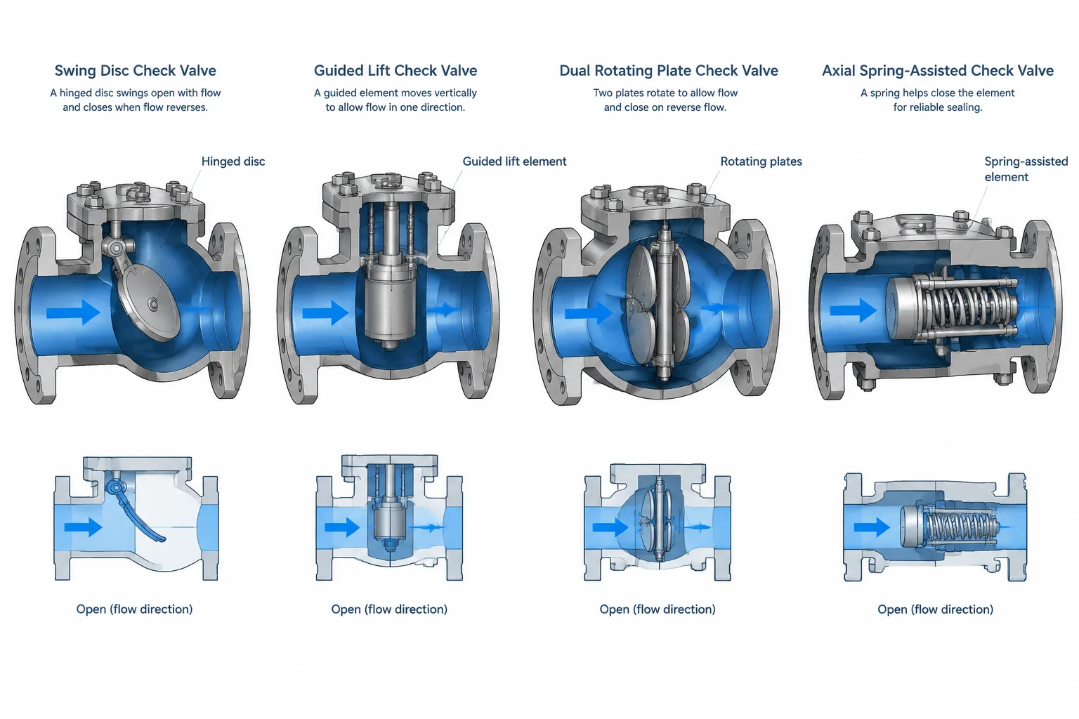
Check valve selection affects more than the valve schedule. The internal closure mechanism influences the external envelope, allowable orientation, connection modeling, maintenance clearance, and information required in a controlled piping component.
This guide compares the CAD and layout implications of swing, lift, dual-plate, and axial check valve designs. It is intended to help designers distinguish functional symbols from physical components and identify which details must be verified before a model is released for procurement, fabrication, or construction coordination.
A check valve allows flow in the intended direction and closes when flow reverses or falls below the condition needed to hold its closure element open. That simple function can conceal major differences in body shape, internal movement, installation orientation, pressure loss, transient response, and maintenance access.
For piping designers and CAD users, selecting a generic symbol or valve body is not enough. A swing check, lift check, dual-plate check, and axial check may share the same nominal line size and end connection while requiring different model geometry and layout checks. The model must communicate the valve actually selected—or clearly show that selection remains unresolved.
Why the check valve type matters in CAD
On a P&ID, check valves are primarily functional devices. The symbol indicates that reverse flow is to be prevented, but it may not fully define the physical construction. In a piping model, however, construction affects the space occupied by the body, cover, hinge, plates, spring mechanism, and connecting joint.
The check valve type can influence:
- face-to-face or end-to-end length;
- body outside dimensions and weight distribution;
- permitted flow direction and installation orientation;
- cover, hinge-pin, or internal-removal access;
- flange bolting and gasket arrangement;
- support and equipment-nozzle loading considerations;
- response to low flow, pulsation, and rapid flow reversal;
- the accuracy of the bill of materials and valve schedule.
A placeholder model may be appropriate during early design, but its status should be visible. Designers should not assume that one generic check valve can be replaced by any other design without affecting adjacent pipe, supports, flanges, or equipment.
Common check valve constructions
Swing check valves
A swing check valve uses a disc that rotates about a hinge. Forward flow moves the disc away from the seat, and reverse flow drives it back toward the closed position. The body commonly includes a cover that provides access to the disc and hinge assembly.
Because disc movement depends on gravity, flow, and the valve’s internal design, installation orientation requires attention. A designer should not rotate a swing check body merely because the external geometry fits better. The approved orientation must come from the applicable valve specification and manufacturer information.
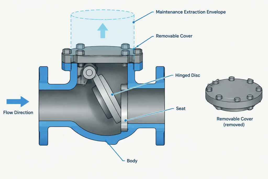
CAD models should represent the body and cover envelope where these features affect clearance. External hinge-pin features, counterweights, levers, or damping devices may create a substantially different envelope from a plain-body valve. If such accessories are part of the selected design, they should not be omitted from interference and access reviews.
Lift check valves
A lift check valve has a closure element that moves away from and back toward its seat along a guided path. Depending on the design, the external body may resemble a globe valve without an operator. Internal geometry typically redirects or constricts the flow path more than a simple full-opening swing arrangement, although actual flow performance must be evaluated from verified product data.
Lift check valves can be sensitive to orientation because the closure element must move correctly within its guide. The acceptable orientation is design-specific rather than a universal rule. The CAD component should therefore include orientation metadata or placement rules when the project catalog supports them.
The upper cover or bonnet area may require access for internal inspection and removal. A geometric model that shows only the pressure-retaining body can miss the vertical extraction space needed to remove internal parts.
Dual-plate check valves
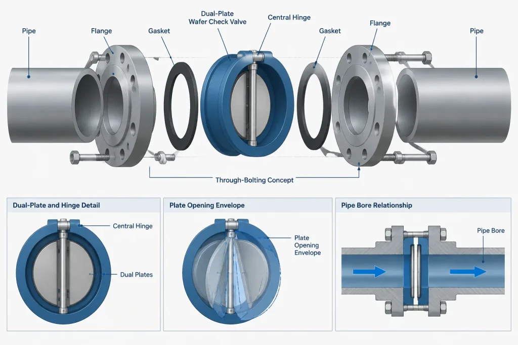
A dual-plate check valve uses two plates that rotate around a central hinge or shaft arrangement. Springs are commonly used to assist closing. Many dual-plate valves are designed as compact bodies installed between mating flanges, although lugged or other body arrangements may also be available.
The compact appearance can be misleading in a CAD model. The valve body must be centered correctly within the flange joint, and the joint definition must account for the actual body and sealing arrangement. Bolting must be based on the complete verified assembly rather than copied from a standard flange-to-flange joint.
Designers must also confirm that the plates have adequate internal clearance relative to the connected pipe bore, flange bore, liners, or adjacent components. Nominal line size alone does not prove that the moving plates can open freely.
Axial or nozzle check valves
An axial check valve generally uses a spring-assisted closure element that moves along the pipeline axis. Its internal flow path and rapid closing action distinguish it from a conventional swing design. These valves may be considered where transient response, stable operation, or compact in-line geometry is important, but selection requires engineering evaluation based on service conditions and verified performance data.
Externally, an axial valve may appear relatively symmetrical. That does not make it reversible. Flow direction remains controlled, and internal construction may affect the required straight-run arrangement or proximity to flow disturbances. Such requirements should come from project engineering and manufacturer documentation, not from the appearance of the CAD solid.
Comparison for layout and model control
| Valve type | Typical closure motion | Key CAD concern | Verification priority |
|---|---|---|---|
| Swing check | Disc rotates about a hinge | Cover, hinge, lever, or counterweight envelope | Orientation, disc movement, and maintenance access |
| Lift check | Closure element moves along a guide | Body height and upper removal space | Permitted mounting position and internal access |
| Dual-plate check | Two plates rotate around a central mechanism | Wafer joint placement, bore clearance, and bolting | Flange compatibility and plate opening clearance |
| Axial check | Closure element moves along the pipe axis | Flow arrow, end planes, and verified body envelope | Flow performance, orientation, and installation guidance |
This comparison describes general construction concepts, not universal selection rules. Products within the same category can have different dimensions, internal mechanisms, installation limitations, and maintenance procedures.
Flow direction must be controlled as data
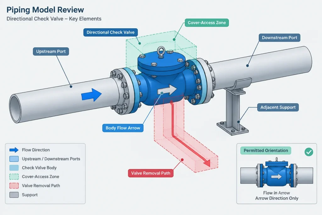
A check valve is directional even when its body looks symmetrical. The component should have a defined upstream port, downstream port, and flow-direction indicator. If a CAD system permits the valve to be mirrored or reversed, the workflow should preserve the intended direction rather than treating the component as an undirected fitting.
Useful checks include comparing the model direction with:
- the process-flow direction shown on the P&ID;
- the line flow arrow on drawings;
- equipment suction and discharge relationships;
- the valve schedule or component record;
- the manufacturer’s body marking and installation instructions.
A reversed check valve may remain visually plausible in a crowded model. Automated direction checks and disciplined review are therefore more reliable than appearance alone.
Installation orientation is not just model rotation
CAD users often rotate valves to resolve clashes or place covers in accessible positions. For a check valve, that rotation may change how gravity acts on the disc or plates, how the shaft is positioned, and whether the internals can operate as intended.
The component catalog can help by storing permitted orientations or displaying a warning when a restricted valve is rotated. Where verified limitations are not yet available, the model should carry a hold or unresolved-design status. It is safer to record the uncertainty than to encode an unsupported assumption into fabrication drawings.
Maintenance and removal envelopes
A valve body envelope identifies occupied space, but it does not necessarily show the space needed to service the valve. Swing and lift designs may require cover removal followed by extraction of the disc, hinge, guide, or other internals. External levers, weights, or damping assemblies may also need room to move or be dismantled.
For compact valves installed between flanges, maintenance may require separating the piping joint and removing the complete valve. The layout should consider whether connected piping can move, whether adjacent equipment prevents withdrawal, and whether temporary support is needed during removal. A narrow body does not automatically make a valve easy to replace.
Data needed for a reliable CAD component
A controlled check valve component should include enough information to distinguish it from a visually similar placeholder. Depending on project practice, useful properties include:
- valve type and internal construction;
- nominal size and end connection;
- material or piping-spec identity;
- upstream and downstream ports;
- face-to-face or end-to-end source;
- body and cover envelope source;
- permitted installation orientation;
- lever, counterweight, damper, or spring configuration;
- manufacturer and model identity when selected;
- revision, approval, and verification status.
Generic dimensional data may be suitable during early layout when it comes from the governing project basis. Final procurement and fabrication coordination should use the dimensions and restrictions applicable to the selected valve.
A practical check valve review workflow
- Confirm the function. Identify what reverse-flow condition the valve is intended to prevent and whether the P&ID defines a particular construction.
- Check the piping specification. Verify the allowed valve type, end connection, materials, and any service-specific restrictions.
- Establish flow direction. Align model ports and the body arrow with the controlled process direction.
- Verify orientation. Do not infer mounting permission from body symmetry or available space.
- Use controlled dimensions. Check end planes, body envelope, cover projection, and accessory geometry against the approved source.
- Review the joint. For wafer and compact bodies, confirm gasket, flange, bore, and bolting compatibility as a complete assembly.
- Check access and removal. Include internal extraction space and the route needed to remove the valve from the line.
- Coordinate supports and loads. Review concentrated weight, nearby supports, and equipment interfaces with the responsible engineering disciplines.
- Record unresolved information. Apply holds or placeholder status until vendor-specific details are verified.
The model should show more than a valve-shaped object
Check valves demonstrate why functional equivalence does not guarantee geometric interchangeability. Swing, lift, dual-plate, and axial designs all resist reverse flow, but they do so with different moving parts and layout consequences.
A useful piping model controls flow direction, orientation, connection geometry, maintenance space, and data status. Treating those attributes as part of the component—not as notes to be resolved later—reduces the risk of reversed installation, inaccessible covers, incompatible flange joints, and late replacement problems.
Managing check valves through model development
The amount of detail assigned to a check valve should match the maturity of the design. During early routing, a generic component may establish approximate connection points and reserve space. As valve selection progresses, that placeholder should be replaced or updated with controlled geometry, direction data, orientation restrictions, joint requirements, and maintenance information.
A useful model-status distinction is whether the component is functional, catalog controlled, or selected-equipment specific. A functional component communicates the need to prevent reverse flow but may not define construction. A catalog-controlled component represents an approved project class or valve type. A selected-equipment-specific component reflects verified information for the valve intended for purchase.
These states should not be confused. A detailed-looking solid can still contain unverified dimensions, while a simple model can be reliable if its limits and approval status are clearly documented.
Coordinate the model with project deliverables
The check valve description should remain consistent across the P&ID, piping specification, valve schedule, model, isometric, and material takeoff. Differences in terminology can cause a generic check valve to be interpreted as a specific construction or allow a selected valve to be replaced with a geometrically incompatible alternative.
- P&ID: communicates process function and controlled flow direction.
- Piping specification: defines permitted construction, materials, connections, and service restrictions.
- Valve schedule: records the identifying and selection information required by the project.
- CAD model: controls connection points, occupied space, orientation, and access envelopes.
- Isometric and material output: must identify the intended component without losing its directional status.
When information conflicts, the discrepancy should be resolved through the project document-control and engineering process rather than by choosing whichever representation appears most detailed.
Use separate geometry for operation and maintenance
Modeling the pressure-retaining body alone may be sufficient for basic visualization, but it is not always sufficient for layout review. Where the CAD platform allows it, designers can manage separate representations for the permanent body envelope, moving external accessories, internal removal space, and the route required to extract the complete valve.
This separation makes clash results easier to interpret. A hard clash with the installed body differs from an overlap with a temporary maintenance envelope, yet both may require action. Clearly classified geometry helps reviewers decide whether routing must change, an obstruction can be removed during maintenance, or access remains unresolved.
Frequently asked questions
Can one generic CAD model represent every check valve type?
A generic model can support preliminary routing if its placeholder status is clear. It should not be treated as proof that swing, lift, dual-plate, and axial designs are geometrically interchangeable. Final coordination requires the approved valve construction and controlled dimensional source.
Why must a check valve have directional ports in the model?
The internal mechanism is designed for flow in a particular direction. Directional ports help preserve that relationship when the component is inserted, mirrored, rotated, exported, or shown on an isometric.
Does a symmetrical valve body mean the valve can be installed either way?
No. External symmetry does not establish internal reversibility. The body flow marking, approved component data, and installation instructions govern direction.
Is valve orientation determined by the check valve category alone?
No. General construction principles can indicate potential concerns, but permitted mounting positions depend on the selected design and verified documentation. Orientation should not be inferred solely from labels such as swing, lift, dual-plate, or axial.
What should be checked for a valve installed between flanges?
Review body centering, sealing arrangement, flange compatibility, bore clearance, bolting, flow direction, and the space needed to separate the joint for removal. The complete assembly must be evaluated rather than the valve body in isolation.
Should maintenance clearance appear as a hard clash in CAD?
Project practice determines how clearance is classified. A practical approach is to keep the installed body and maintenance envelope in distinct model categories so reviewers can distinguish permanent interference from access or removal conflicts.