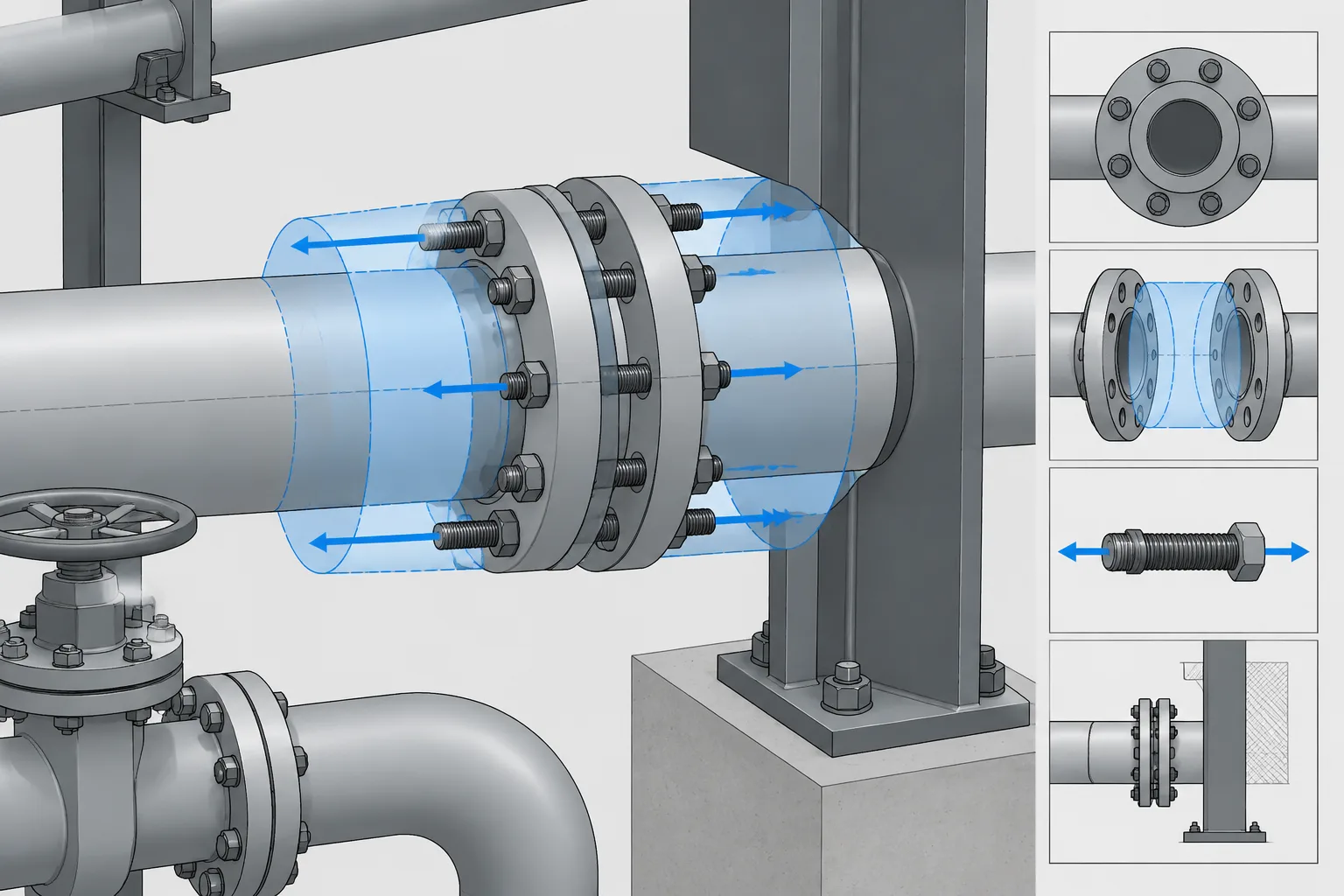
Flange joint separation clearance should be evaluated as a maintenance sequence, not simply as open space around an installed connection. A useful CAD review asks what will be removed, which side of the joint can move, where the fasteners will go, and how the disconnected piping or component will be supported.
This guide explains how to represent those temporary conditions without treating a clearance envelope as a final maintenance procedure. It is intended to help piping designers, CAD users, and reviewers distinguish normal operating geometry from the space needed to open and service a flanged joint.
A flanged joint may fit perfectly in the operating model yet still be difficult to open for maintenance. The assembled geometry shows flange faces, gasket location, bolting, and connected components, but it does not automatically show how the joint will be separated. Maintenance personnel may need room to remove studs, spread the flanges, extract a gasket, clean the facing surfaces, and install a replacement without damaging adjacent equipment or piping.
Flange joint separation clearance is therefore more than an empty space beside the joint. It involves axial movement, tool access, component support, and a realistic understanding of which parts of the piping system can move after the bolts are released. Addressing these questions during layout can prevent a nominally removable valve or spool from becoming trapped in place.
What flange joint separation clearance means
Separation clearance is the space and movement needed to take an assembled flanged joint apart. The required maintenance action determines which clearances matter. Replacing a gasket, removing a valve, installing a line blind, and disconnecting an equipment nozzle can each create a different disassembly problem.
The relevant clearances may include:
- Axial separation: movement perpendicular to the flange faces so the faces no longer clamp the gasket or removable component.
- Radial access: room around the outside of the joint for tools, hands, lifting devices, and gasket handling.
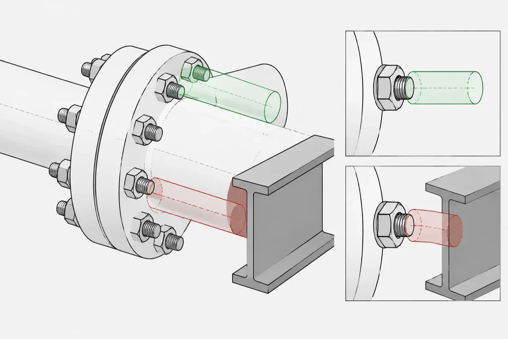
- Stud extraction space: a clear path along the bolt axis when studs or bolts cannot remain in the flanges.
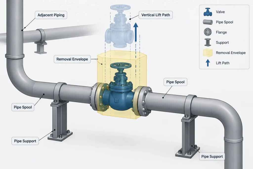
- Component removal space: an extraction path for a valve, spool, spectacle blind, strainer, or other item between the flanges.
- Support space: room for temporary supports, rigging, jacks, approved flange-separation equipment, or other maintenance provisions.
These spaces are related but not interchangeable. A joint can have generous radial access while having no practical axial movement. Similarly, a valve may have an apparent lifting path even though long studs cannot be withdrawn because a wall or structural member blocks them.
Why the assembled CAD model can hide the problem
Most piping models represent the installed condition. Flanges are shown at their assembled face locations, the gasket is represented within the joint, and bolting may be simplified. This is appropriate for routing, material reporting, and many clash checks, but it can conceal the disassembly sequence.
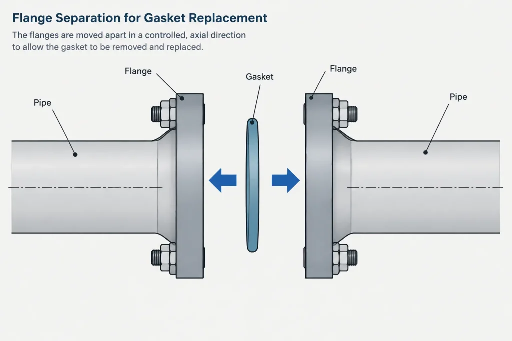
Two connected flange faces cannot separate unless something else moves. Depending on the arrangement, movement may come from a removable spool, piping flexibility, an intentionally provided break joint, equipment removal, or temporary displacement after supports are released. It should not be assumed merely because the joint is bolted rather than welded.
Common hidden constraints include:
- Pipe supports that prevent axial movement.
- Guides, stops, anchors, or connected branches that restrain the line.
- Equipment nozzles that must not be used as reaction points.
- Closely spaced elbows or rigid spool geometry.
- Insulation, cladding, heat tracing, or removable covers around the joint.
- Platforms, walls, cable trays, and structural bracing near the bolt axes.
- Valve operators or instrument tubing occupying the intended extraction path.
Different maintenance tasks create different clearance needs
| Maintenance task | Primary clearance concern | CAD review question |
|---|---|---|
| Gasket replacement | Face separation and access to both seating surfaces | Can the faces be opened and cleaned without forcing connected piping? |
| Stud or bolt removal | Clear path along the fastener axis | Do structure, piping, insulation, or equipment block withdrawal? |
| Valve removal | Axial release plus lifting or lateral extraction | Can the valve clear the studs, flange faces, operator, and nearby objects? |
| Blind installation | Face separation, handling access, and correct joint stack-up | Can the isolation item be inserted and positively identified in service? |
| Nozzle disconnection | Controlled piping movement and protection of equipment | Is the connected spool independently supported during disassembly? |
A useful review begins by naming the intended task. A generic note such as “provide maintenance clearance” does not define whether the designer is protecting a bolt-removal path, a valve extraction envelope, or room to service the gasket faces.
Axial movement is a system question
The geometry at one flange cannot establish whether the joint will open. The designer must review the connected piping as a system. A short spool between two rigid equipment nozzles may have almost no available axial movement. A longer run may appear more flexible, but branches and supports can still lock it in place.
For a planned break joint, identify which side is expected to move and what must be disconnected or released first. Consider the weight of the moving segment, its center of gravity, attached small-bore connections, insulation, and the effect of removing nearby support restraints. Stress, support, equipment, and maintenance disciplines may all need to participate in the review.
CAD should not imply that piping can be forced aside simply because a modeled clash disappears when a component is hidden. Movement during maintenance is a temporary load case with real consequences. The allowable method must be established by the project and verified against the actual system.
Stud removal and bolting direction
Bolting access is often reviewed only for wrench clearance, but disassembly can require a longer unobstructed path. A stud may remain through both flanges while the nuts are removed, or it may need to be withdrawn before the component can move. Machine bolts also have a preferred insertion and removal direction when one side of the joint is obstructed.
When detailed maintenance review is required, the model or drawing can indicate the intended fastener withdrawal direction. This is especially helpful near concrete walls, structural columns, equipment casings, closely packed parallel lines, and valve operators. Simplified bolting geometry should not be treated as proof that the actual selected fasteners can be removed.
Gasket removal is not just an opening-width check
Once the flanges are separated, personnel need access to remove the old gasket and inspect or clean the facing surfaces. A gasket that can theoretically pass through a narrow opening may still be difficult to handle without scraping or bending it. Facing type, gasket construction, joint orientation, and maintenance procedure all influence the practical requirement.
Vertical joints can present different handling issues from horizontal joints. Large or flexible gaskets may need temporary retention during installation. Insulation around the flange may also need to be removed before work begins. The required opening and handling method should come from the applicable project procedure, component information, and maintenance planning rather than from a generic CAD assumption.
Modeling a maintenance envelope
Not every project needs full disassembly animation. A simple, controlled envelope can communicate the important space claim without overloading the production model.
Recommended envelope elements
- An axial zone showing the intended direction of flange separation.
- Bolt or stud withdrawal cylinders where surrounding congestion is a concern.
- A removal envelope for valves, blinds, spacers, or removable spools.
- A lifting path or laydown zone for heavy components.
- Temporary support or rigging space where it affects layout.
Place these objects on a dedicated maintenance or clearance layer and distinguish them from physical components. Add metadata or notes explaining the assumed task and movement direction. An unlabeled transparent volume can otherwise be mistaken for insulation, operating travel, or a generic keep-out zone.
Clearance objects should be treated as design aids, not verified maintenance instructions. Final dimensions and procedures depend on the selected component, bolting arrangement, gasket, site conditions, and approved work method.
Practical CAD review workflow
- Identify the break joint. Mark the flange pair expected to be opened rather than reviewing every flange as if it has the same maintenance role.
- Define the task. State whether the purpose is gasket service, component removal, isolation, inspection, or equipment disconnection.
- Select the moving side. Trace the connected piping to supports, branches, anchors, and equipment interfaces.
- Check fastener paths. Review actual or conservatively represented stud and bolt envelopes in both possible directions.
- Create the removal envelope. Include the component body, projections, operator, lifting attachments, and necessary change in orientation.
- Review temporary conditions. Consider support loss, center-of-gravity changes, open pipe ends, and disconnected small-bore items.
- Coordinate the result. Record assumptions and unresolved items for piping, structural, mechanical, stress, and maintenance review.
Documentation and model-control practices
Maintenance assumptions should not exist only in a designer’s working view. Important break joints can be identified on layout drawings, model review reports, equipment-removal studies, or project-specific maintenance plans. The documentation should distinguish verified information from preliminary space reservations.
If vendor dimensions or maintenance instructions are unavailable, use a clearly labeled hold or conservative placeholder rather than presenting an estimated envelope as final. Recheck the space after component selection, support development, insulation definition, and structural coordination. A late change in valve operator, bolting, or adjacent steel can invalidate an earlier review.
Key takeaway
A flange is detachable in principle, but the connected piping arrangement determines whether it is maintainable in practice. Effective flange joint separation clearance accounts for face movement, gasket handling, fastener withdrawal, component extraction, support changes, and safe access. By modeling the intended maintenance sequence rather than only the assembled joint, piping designers can expose constraints early and create layouts that are easier to inspect, isolate, and repair.
Turning a clearance check into a design decision
A maintenance envelope is most useful when it records a specific assumption. The model object or review note should identify the intended break joint, the maintenance task, the expected movement direction, and any dependency on removable supports, insulation, adjacent piping, or structural access.
Separate the space claims
- Occupied space: the physical volume of the assembled flanges, gasket, bolting, insulation, and connected component.
- Access space: the area needed for personnel, tools, inspection, cleaning, and handling.
- Movement space: the temporary swept volume created while fasteners, piping, or equipment are repositioned.
- Support space: the area reserved for approved lifting, restraint, or temporary support arrangements.
Keeping these categories distinct makes coordination comments easier to resolve. An object that clears the installed valve may still obstruct a stud-withdrawal path, while an open lifting route may not provide enough access to clean the flange faces.
Questions to close during review
- Is the modeled joint intended to be opened in place?
- Which connected section is permitted to move after the fasteners are released?
- Do supports, branches, equipment nozzles, or nearby components restrict that movement?
- Can the selected fasteners be removed in the assumed direction?
- Is there a defined handling route for the gasket or removable component?
- Are temporary support and rigging assumptions visible to the reviewing disciplines?
- Has the envelope been identified as preliminary or verified?
The answer should be based on the selected components, project procedures, support philosophy, and coordinated maintenance plan. CAD geometry can reveal conflicts and preserve space, but it does not authorize piping displacement, flange spreading, lifting, or equipment loading.
Frequently asked questions
Does a bolted flange automatically provide a removable joint?
No. Bolting allows the connection to be released, but removal still depends on available movement, fastener access, component support, and an unobstructed extraction path.
Is wrench clearance the same as stud-removal clearance?
No. Wrench clearance provides access to turn or hold a fastener. Stud-removal clearance requires a continuous path along the fastener axis and may extend into nearby structural, equipment, piping, or insulation space.
Can standard clash detection verify flange maintainability?
Clash detection can identify conflicts with a modeled maintenance envelope, but the result is only as reliable as the assumptions represented. It does not establish that the connected piping can safely move or that the planned disassembly method is acceptable.
How should preliminary clearance be modeled when component details are unavailable?
Use a clearly identified placeholder or design hold based on the project review process. Do not present an estimated volume as verified. Update the envelope when component, bolting, insulation, support, and handling information becomes available.
Which side of a flange joint should move during disassembly?
There is no universal answer. The intended moving side must be established from the piping arrangement, support conditions, branches, equipment interfaces, component weight, and approved maintenance method.
Should insulation be included in the review?
Yes. Insulation, cladding, tracing, and removable covers can obstruct tools and handling paths. The review should also establish whether those items are expected to be removed before the joint is opened.
Who should review a critical flange separation plan?
The required participants depend on the project, but piping layout, mechanical, stress, support, structural, equipment, and maintenance personnel may all have relevant responsibilities. Assumptions and unresolved constraints should be documented for coordination.