Socket-weld piping CAD requires more than connecting a pipe centerline to a fitting port. The visible route may be correct while the concealed pipe engagement, physical pipe endpoint, or reported cut length remains incorrect.
The key is to distinguish component geometry from assembly requirements. Socket depth describes the fitting, insertion describes the pipe position, and the assembly gap is a controlled fit-up condition. A CAD library must keep these concepts separate before its geometry can support fabrication output.
This guide explains how those relationships affect fitting takeout, spool dimensions, isometric presentation, and cut-length reporting. It also identifies the checks needed before model data is released for fabrication.
Socket-weld piping can look simple in a CAD model: place a fitting, route a pipe centerline into it, and add a weld. The fabrication geometry is less obvious. Part of the pipe is concealed inside the fitting socket, the pipe end may not be intended to remain against the internal shoulder, and the fitting dimensions used for layout are not automatically the same as the dimensions needed for cutting.
A reliable socket-weld piping CAD workflow separates three related ideas: the fitting’s published geometry, the required assembled position of the pipe, and the resulting pipe cut length. Reference tables provide the authoritative component dimensions. The CAD model must use those dimensions consistently without turning nominal database geometry into an unsupported fabrication assumption.
How a socket-weld connection is assembled
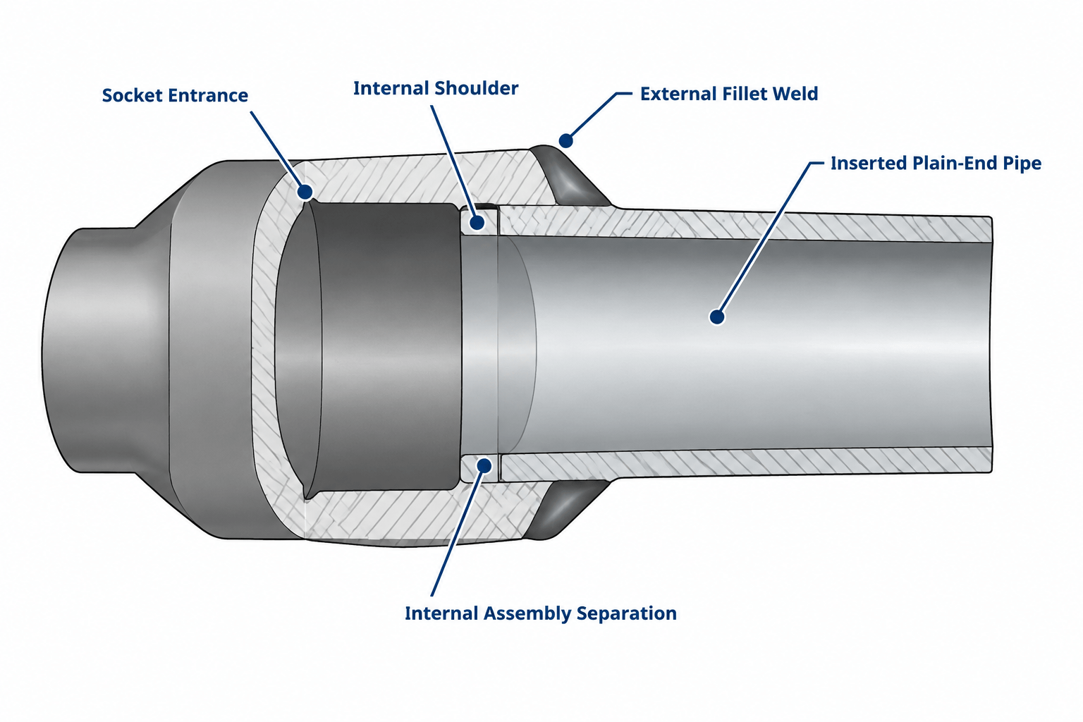
A socket-weld fitting has a recessed opening that receives the plain end of the pipe. Inside the fitting, a shoulder establishes the physical limit of the socket. A fillet weld is then made around the outside of the connection.
The important geometric features are:
- Socket entrance: the external opening where the pipe enters the fitting.
- Socket shoulder: the internal surface that limits full insertion.
- Socket depth: the axial distance available between the entrance and shoulder.
- Pipe insertion: the portion of the pipe concealed inside the fitting.
- Assembly gap: the intended separation, when required, between the pipe end and internal shoulder in the completed fit-up.
- External fillet weld: the weld around the pipe at the fitting entrance.
The assembly gap should not be confused with the visible space outside the fitting. It is an internal fit-up condition and may be impossible to inspect visually after welding. Its value and verification method belong to the governing fabrication procedure, project specification, and applicable piping requirements.
Why centerline geometry is not enough
A centerline model can establish routing, fitting locations, and overall coordination while hiding the socket engagement completely. Two models may therefore look identical even though their implied pipe cut lengths are different.
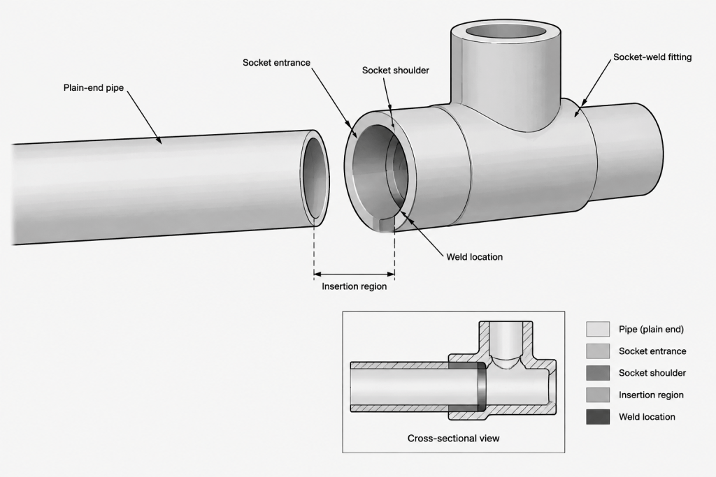
If a pipe segment is trimmed to the outside face of each socket, it is too short to represent the material inserted into the fittings. If it extends to each internal shoulder, it may represent full socket depth rather than the intended assembled position. Neither interpretation should be accepted merely because the centerline route is correct.
For fabrication-level work, define where each modeled pipe endpoint represents:
- the socket entrance;
- the fitting shoulder;
- the intended pipe-end position;
- or an abstract connection point used only by the CAD system.
This endpoint convention should be consistent across component libraries, cut-length reports, isometrics, and spool drawings.
Socket depth, insertion, and assembly gap
Socket depth is a fitting dimension. Actual pipe insertion is an assembly condition. They are related, but they are not always interchangeable.
Conceptually, the intended insertion equals the available socket depth minus the specified internal separation. That relationship should be implemented only with verified component data and approved fit-up requirements. A generic CAD default should not be treated as authoritative for every material, fitting type, or project.
Some fabrication procedures establish the gap by initially placing the pipe against the shoulder and then repositioning it before welding. Other workflows may use a controlled tool, spacer, mark, or documented shop method. The drawing should communicate the required final condition without prescribing an unapproved fabrication technique.
Useful CAD parameters
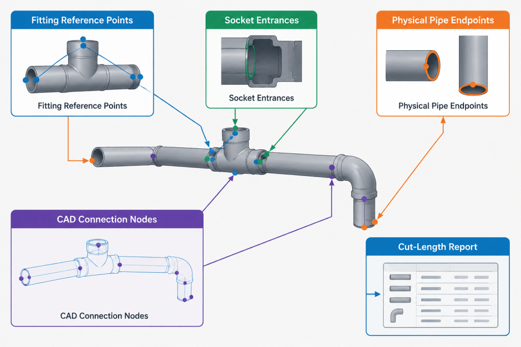
A parametric socket-weld component can keep the following values separate:
- center-to-end or end-to-end layout dimension;
- socket entrance location;
- shoulder location;
- reference socket depth;
- intended insertion allowance;
- weld location;
- pipe cut endpoint; and
- connection node used for model connectivity.
Separating these parameters prevents a change to symbolic graphics from unintentionally changing reported cut lengths.
Calculating pipe cut length conceptually
For a straight pipe between two socket-weld components, begin with a controlled distance between known fitting reference points. Convert that layout distance into a cut length by accounting for the fitting geometry at both ends and adding the verified pipe insertion into each socket.
The exact calculation depends on the reference points used by the CAD library. A model based on fitting centers requires different takeout logic from one based on socket entrances or connection nodes. The formula should therefore be documented as part of the library definition rather than improvised during detailing.
| Reference method | What the dimension controls | Main cut-length risk |
|---|---|---|
| Fitting center to fitting center | Overall routed geometry | Incorrect or inconsistent fitting takeout |
| Socket entrance to socket entrance | Visible pipe span between fittings | Omitting concealed insertion at one or both ends |
| Pipe end to pipe end | Direct cut length | Embedding an unverified assembly-gap assumption |
| CAD connection node to connection node | Software connectivity | Assuming the node matches a physical fabrication point |
Do not measure a rendered solid and assume the result is the pipe cut length. The model may include overlaps, hidden engagement, simplified fitting cavities, or connection nodes placed for software behavior rather than fabrication accuracy.
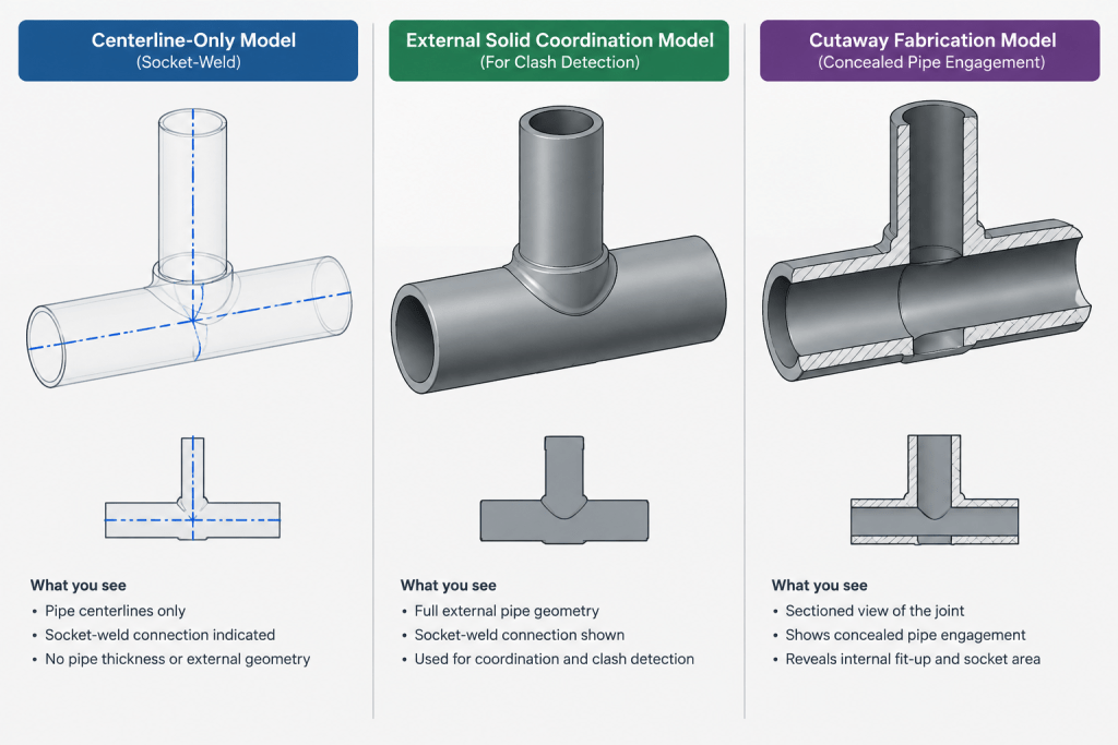
How much detail should the CAD model show?
Schematic or early layout models
A simplified fitting envelope and centerline connection may be sufficient for routing studies. At this level, cut lengths should not be extracted unless the component rules are specifically configured for that purpose.
Coordination models
External fitting geometry, pipe outside diameter, weld envelope, and access space may be useful. Internal sockets can remain simplified if their omission is documented and does not affect generated fabrication data.
Fabrication models and spool drawings
The model or associated data should distinguish the physical pipe end from the fitting connection point. It should also preserve the approved insertion logic used to calculate cut lengths. The drawing does not need to display every internal surface in every view, but the underlying values must be traceable.
Drawing and isometric presentation
In a typical piping isometric, the socket itself may be represented symbolically rather than as a cutaway. A general note or connection-specific callout can state that socket-weld joints require fit-up in accordance with the approved project procedure. Avoid placing an assumed gap value on drawings unless it has been verified for the applicable work.
Enlarged details are useful when a drawing must clarify:
- which end of a component is socket-welded;
- where the pipe cut endpoint is located;
- how a special fitting differs from the standard library component;
- whether a nearby weld is socket, butt, seal, or attachment welding; or
- how the joint interfaces with a threaded, flanged, or welded transition.
Weld symbols, if used, should describe the external weld without implying that the pipe is welded to the internal shoulder.
Common socket-weld CAD errors
- Stopping pipe at the fitting face: the reported piece omits the concealed engagement.
- Extending pipe automatically to the shoulder: the model assumes full insertion without considering the approved fit-up condition.
- Using one insertion value for every fitting: component geometry may vary by size, type, source, or governing specification.
- Double-counting insertion: the solid pipe already extends into the fitting, but the report adds a second insertion allowance.
- Confusing takeout with socket depth: center-to-end layout geometry and internal engagement describe different parts of the fitting.
- Ignoring mixed-end components: a valve or adapter may use different connection logic at opposite ends.
- Scaling a generic CAD block: visual scaling can distort socket geometry and disconnect it from verified tabular data.
A practical checking workflow
- Confirm the connection type. Verify that each end is actually socket-welded rather than threaded, butt-welded, or represented by a generic symbol.
- Verify component dimensions. Use the site’s authoritative reference data, approved project library, or controlled manufacturer information as applicable.
- Identify CAD reference points. Determine what the fitting origin, port, and pipe endpoint physically represent.
- Review insertion logic. Confirm that the modeled or calculated insertion reflects the approved assembly condition.
- Recalculate a sample piece independently. Compare a manually checked cut length with the CAD-generated value.
- Check both ends separately. Do not assume that opposite ends use identical fitting types or takeout rules.
- Inspect the bill of materials. Confirm that fitting descriptions and end connections match the geometry.
- Record the modeling basis. State whether internal socket geometry is physical, simplified, or data-driven.
Keep reference data and fabrication assumptions separate
Dimension tables answer questions about nominal component geometry. They do not, by themselves, define a project’s welding procedure, fit-up practice, inspection method, or acceptable fabrication tolerance. CAD authors add value by connecting verified fitting dimensions to transparent modeling rules while keeping those other requirements under proper engineering and fabrication control.
The most dependable socket-weld piping CAD model is not necessarily the one with the most detailed solids. It is the one in which every connection point, insertion allowance, and reported cut length has a clear definition that can be checked against authoritative data and approved project requirements.
From CAD connection to fabrication instruction
A CAD connection node primarily allows components to connect and route correctly. It becomes a fabrication reference only when the library documents its physical meaning and applies verified fitting geometry. A port located at a fitting face, socket entrance, shoulder, or abstract routing point will produce different results if the same cut-length rule is applied without adjustment.
This distinction is especially important when model graphics and report logic are maintained separately. A simplified fitting may still generate dependable output when its data rules are controlled. Conversely, a detailed solid can produce an incorrect cut list if its pipe endpoint or takeout definition is wrong.
Information that should remain traceable
- Component source: Identify the controlled reference behind the fitting geometry.
- Connection-point definition: Document what each CAD port represents physically.
- Insertion basis: Separate published socket geometry from the approved assembled pipe position.
- Cut-length rule: State how fitting takeout and concealed engagement are included.
- Output behavior: Confirm whether drawings and reports read geometric endpoints, stored parameters, or calculated values.
- Revision control: Recheck affected pipe pieces when a component definition or fit-up basis changes.
Reviewing a socket-weld spool before release
The most useful review compares the route, component definitions, and fabrication output rather than checking only the rendered assembly. Select a representative pipe piece and follow its reported length back through the reference points and insertion rules used at each end.
Mixed-end fittings deserve particular attention because the connection behavior may not be symmetrical. A valid rule for the socket-weld end should not be applied automatically to a different end connection. The same caution applies when replacing a generic component with a controlled library part.
Questions for the model review
- Does the pipe endpoint represent the actual cut end or only a routing connection?
- Is concealed pipe engagement already present in the geometry, the calculation, or both?
- Does the fitting takeout use the same reference convention as the routed dimension?
- Is the assembly condition based on an approved requirement rather than a software default?
- Can a checker reproduce the reported cut length without measuring the rendered solid?
- Will a component substitution trigger an appropriate cut-length review?
A clear answer to these questions makes the model easier to audit and reduces the risk that nominal component geometry will be mistaken for a complete fabrication instruction.
Socket-Weld Piping CAD FAQ
Is socket depth the same as pipe insertion?
No. Socket depth is part of the fitting geometry. Pipe insertion describes the assembled position of the pipe within that socket and may also depend on the approved fit-up condition.
Why can a correct centerline route produce a wrong cut length?
Centerline routing establishes component locations but may not show where the physical pipe ends occur. Incorrect takeout, omitted engagement, or an abstract CAD connection point can therefore affect the reported cut length.
Should the pipe solid stop at the socket entrance?
Not automatically. Stopping there omits the concealed portion of the pipe unless the software adds that engagement through a verified calculation. The geometry and reporting method must use the same documented convention.
Can the pipe be modeled to the internal shoulder?
Only when that endpoint correctly represents the approved modeling and assembly basis. Extending the pipe to the shoulder without considering the required fit-up condition can embed an unsupported assumption.
Does a fabrication model need a fully detailed internal socket?
Not necessarily. Simplified internal geometry can be acceptable when the physical pipe endpoint, insertion logic, and cut-length calculation remain defined and traceable.
Can cut length be obtained by measuring the CAD solid?
That approach is unreliable unless the library explicitly defines the solid endpoints as physical cut ends. Hidden overlaps and software connection behavior may make the measured geometry differ from fabrication output.
Where should an assembly-gap requirement come from?
It should come from the governing project requirements, approved fabrication procedure, and applicable piping criteria. A generic CAD setting should not be treated as the controlling requirement.