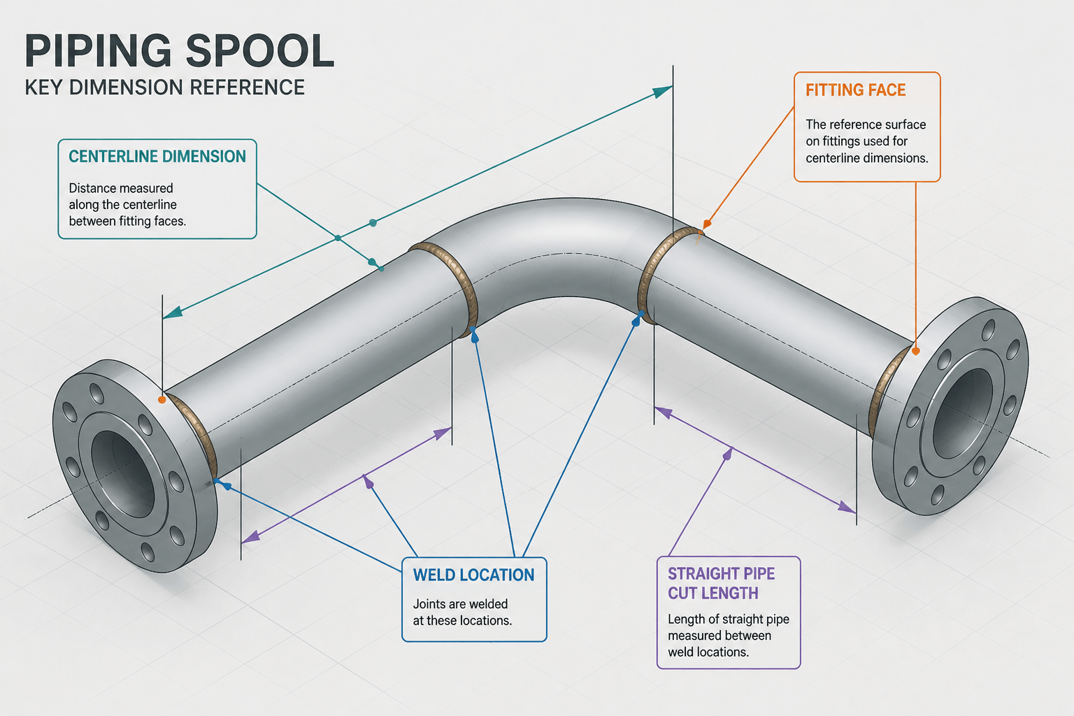
In piping design, a dimension can be correct for layout and still be unsuitable for cutting material. The distinction between a route measurement and a fabrication length matters whenever an isometric, CAD model, spool drawing, or bill of material is used by different project teams.
This guide explains how to identify the measurement basis, relate CAD geometry to physical connection points, and review the component and joint information needed before releasing a cut list. The goal is not to replace approved project data, but to make the drawing’s intent easier to interpret.
A piping drawing can show a clear route and still leave an important question unanswered: what length should be used to cut the straight pipe? The distance measured in CAD is not always the same as the fabrication length, and neither may represent the final installed dimension.
This difference is normal when the drawing combines centerline geometry, fitting dimensions, weld preparation, flange locations, insulation requirements, and field-fit decisions. The key is to understand what each dimension represents before using it for a material takeoff, spool drawing, fabrication cut list, or installation check.
What is a piping takeoff dimension?
A takeoff dimension is a measurement used to establish the location of a component feature from a reference point. Depending on the drawing convention, it may be taken to a pipe centerline intersection, fitting face, flange face, weld location, branch center, or equipment connection point.
In an isometric or model, a takeoff may help define the position of an elbow, valve, flange, support, or connection. It is primarily a layout and coordination value. It does not automatically define the length of straight pipe that must be cut.
Always check the drawing’s dimensioning convention. A dimension to the center of an elbow is not interchangeable with a dimension to the elbow face. Similarly, a flange location may be measured to its face, bolt center, or pipe-end weld location depending on the project’s drafting practice.
Why a CAD measurement may not equal a cut length
CAD geometry usually represents the design route. Fabrication requires the physical length between actual connection features after fitting geometry and joint details are considered. Several factors create a difference:
- Fitting takeout: An elbow, tee, reducer, or other fitting occupies part of the route. The straight pipe length is found by subtracting the relevant fitting dimensions from the overall route distance.
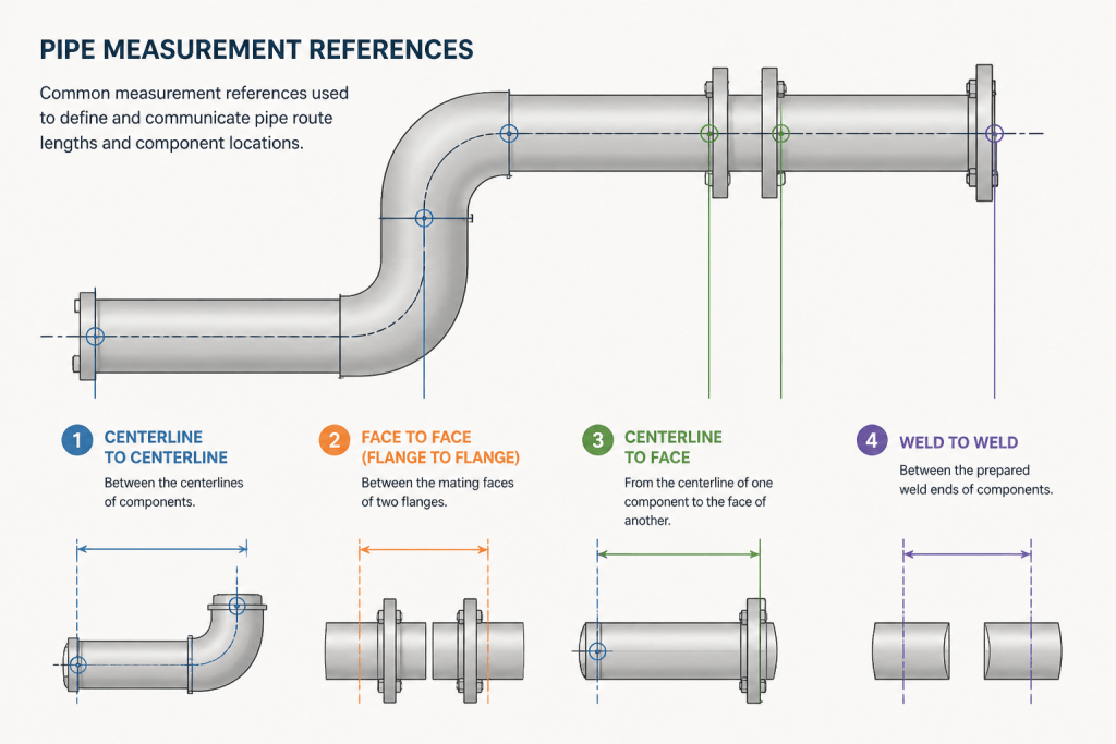
- Connection reference: A model may measure between centerlines, while fabrication needs a face-to-face, weld-to-weld, or flange-to-weld distance.
- Weld preparation: The location of the finished weld is not necessarily the same as the nominal end of the pipe or fitting.
- Gasket and flange details: A flanged connection has a defined face location, but the pipe cut may terminate at a weld location behind that face.
- Joint gaps and fit-up: The fabrication method may require a project-defined gap, root preparation, or adjustment allowance.
- Field-fit conditions: A spool may intentionally leave one connection for field measurement or final adjustment.
- Model simplification: A CAD block may show a symbol or envelope without representing every physical feature used in fabrication.
Common measurement references in piping drawings
| Reference | What it describes | Typical use |
|---|---|---|
| Centerline to centerline | Distance between geometric pipe-axis intersections | Routing, elevations, and design coordination |
| Face to face | Distance between fitting, flange, valve, or equipment faces | Layout checks and connection coordination |
| Centerline to face | Distance from a pipe-axis intersection to a component face | Fitting placement and spool calculations |
| Weld to weld | Distance between specified weld locations | Fabrication and spool detailing |
| End to end | Overall physical extent of a pipe or component | Material descriptions and dimensional checks |
These references are related, but they are not substitutes for one another. A drawing should make the intended reference obvious through dimension extension lines, component symbols, notes, or a stated project convention.
How to calculate a straight-pipe cut length conceptually
The basic process is to start with the distance between the two physical connection references and remove the portions occupied by fittings or other components. The result must then be checked against the joint configuration.
For example, a straight segment between two elbows may be shown as a centerline distance. To determine the pipe piece, identify the applicable takeout from each elbow and subtract those takeouts from the centerline distance. If one end terminates at a flange, valve, or reducer, use the dimension associated with that component’s actual connection reference rather than assuming the component symbol reaches the pipe cut line.

This is a calculation method, not a universal formula. The correct inputs come from the approved component data, piping specification, fabrication practice, and spool drawing convention. Do not use a generic block dimension when the project’s component library or reference table provides a different value.
CAD workflow for checking takeoffs and cut lengths
1. Confirm the component identity
Verify the size, component type, end connection, pressure class where applicable, material designation, and orientation. A visually similar fitting can have a different takeout or connection geometry.
2. Identify the measurement reference
Read the dimension endpoints carefully. Determine whether the value runs between centerlines, faces, weld locations, or equipment connection points. If the endpoints are ambiguous, add a clearer witness dimension or explanatory note.
3. Separate route dimensions from fabrication dimensions
Keep centerline and coordinate dimensions available for installation and model coordination, but do not label them as cut lengths unless they have been adjusted for the physical components and joint details.
4. Apply fitting takeouts from controlled data
Use the project-approved component library, manufacturer information, or authoritative local reference data. Check that the CAD block’s insertion point matches the dimension convention used by the drawing and the fabrication software.
5. Check weld and field-fit intent
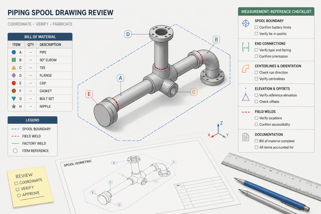
Review weld IDs, spool boundaries, field weld indicators, and any notes identifying an adjustable or field-measured connection. A cut list that ignores a planned field fit can create an installation problem even when the model geometry appears correct.
6. Compare the result with the bill of material
The bill of material should identify the pipe item and quantity consistently with the spool or isometric. Length descriptions should not mix nominal route dimensions with fabrication cut dimensions without clear labeling.
Drafting practices that prevent confusion
- Use distinct labels for route dimensions, component dimensions, and fabrication lengths.
- Dimension to recognizable physical features instead of relying only on crowded model geometry.
- Show spool breaks and field welds where they affect the measurement basis.
- Keep fitting insertion points consistent across the CAD library.
- Document whether dimensions are nominal, theoretical, or adjusted for fabrication.
- Review small-bore branches and instrument connections separately because their fittings may use different modeling conventions.
- Do not hide a required adjustment inside an unexplained dimension override.
Review checklist
Before releasing a cut list or spool drawing, ask:
- Are both dimension endpoints clearly identified?
- Does each fitting use the correct approved takeout?
- Are flange faces, weld locations, and equipment connections distinguished?
- Are weld gaps, preparation details, and field-fit requirements defined by the project?
- Does the spool boundary agree with the isometric and model?
- Do the pipe lengths and component quantities reconcile with the bill of material?
- Would a fabricator interpret the measurement without guessing?
Key takeaway
Piping takeoff dimensions describe where components belong; fabrication cut lengths describe what must be produced. The two values can match in a simple straight run, but they often diverge when fittings, flanges, welds, and field adjustments are involved. A reliable CAD workflow makes the measurement reference explicit, applies controlled component data, and keeps design dimensions separate from fabrication dimensions.
How to read the measurement basis before measuring in CAD
Before taking a measurement, identify what the drawing is trying to control. A routing dimension supports coordination and placement, while a fabrication dimension supports production. These purposes can appear on the same drawing, but they should not be treated as interchangeable.
Start at the dimension endpoints rather than at the visible pipe line alone. Look for the feature represented by each endpoint, such as an axis intersection, fitting face, flange face, weld location, or equipment connection. Then confirm that the component shown in the model uses the same insertion and connection convention as the drawing.
Why the distinction matters across project deliverables
A piping model, isometric, spool drawing, fabrication cut list, and bill of material may describe the same run from different viewpoints. Coordination documents emphasize location and connectivity. Fabrication documents must account for the physical portions occupied by components and the way joints will be made. Installation documents may also identify a field-fit connection or a measurement that must be verified at the site.
Problems commonly arise when a route dimension is copied directly into a cut list, when a simplified CAD block is mistaken for fabrication geometry, or when a flange face is confused with the pipe-end weld location. Clear labels and consistent component data reduce these interpretation errors.
Practical review principle
Treat every length as having a defined reference basis. If the basis is not obvious, resolve the ambiguity before fabrication or procurement work proceeds. The drawing should make it possible to distinguish design intent, component geometry, joint preparation, spool boundaries, and any deliberate field adjustment.
Frequently asked questions
Is a CAD route measurement the same as a pipe cut length?
Not necessarily. A CAD route measurement may run between centerlines or other layout references, while a cut length must account for fitting geometry, connection locations, weld details, and any project-defined fit-up condition.
Why do fitting takeouts affect straight-pipe lengths?
A fitting occupies part of the modeled route. The straight pipe piece therefore represents the remaining distance between the applicable physical connection references, not automatically the full centerline distance.
Should a flange-to-flange dimension be used as the pipe cut length?
Only when the drawing and fabrication convention establish that basis. The pipe may terminate at a weld location behind the flange face, so the flange reference and pipe cut reference must be distinguished.
How can a drafter make takeoff dimensions clearer?
Use recognizable endpoints, consistent CAD insertion points, separate labels for route and fabrication dimensions, and clear indications for spool breaks, welds, and field-fit connections.
What should be checked before issuing a piping cut list?
Confirm the component identity, measurement reference, approved fitting data, weld and fit-up intent, spool boundary, and agreement between the spool drawing, isometric, model, and bill of material.
Why can similar-looking fittings produce different results?
Fittings that appear similar may differ in connection geometry, end configuration, orientation, or approved dimensional data. The component identity and controlled project data should be verified before calculating a fabrication length.