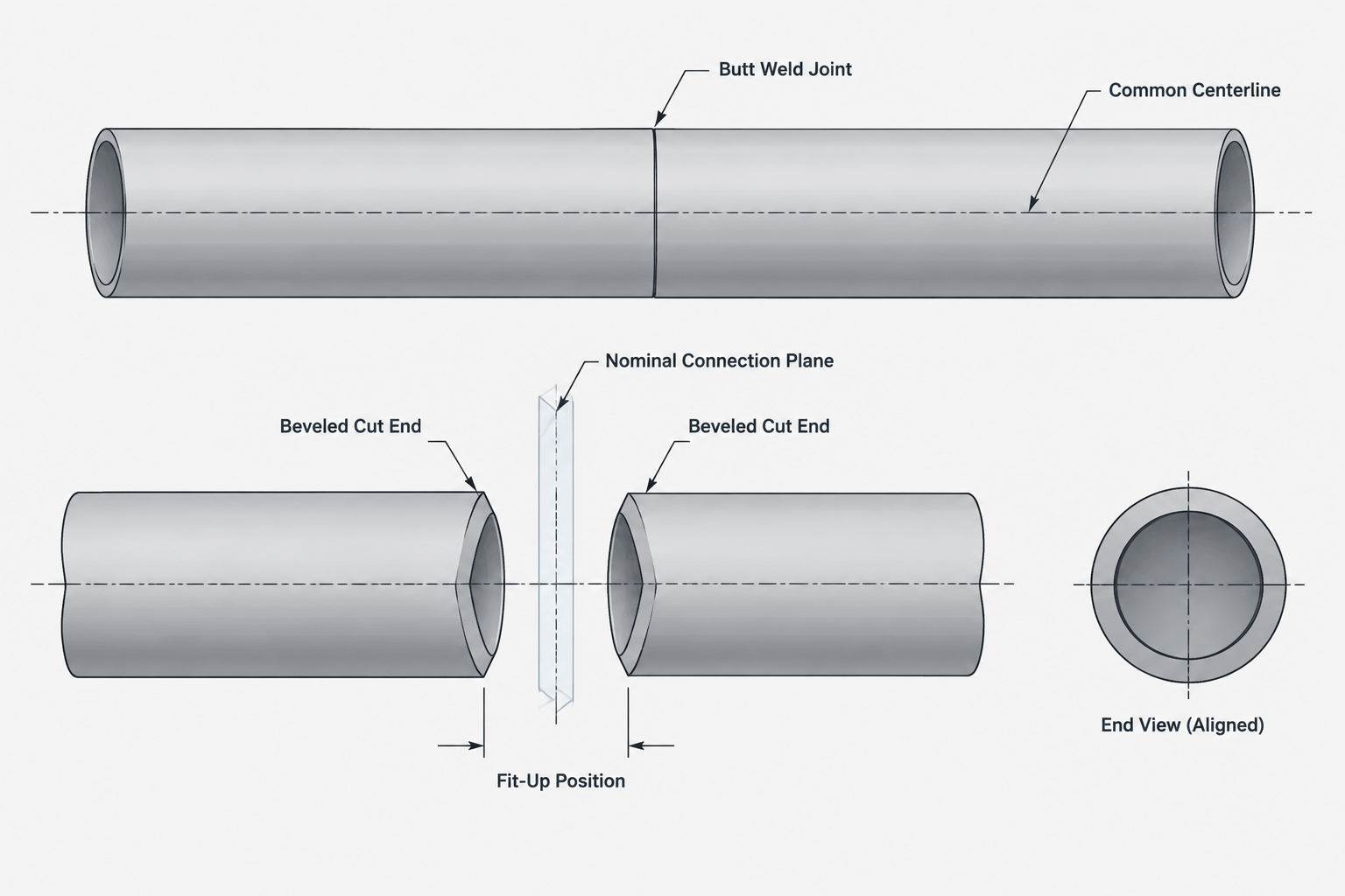
Pipe weld end preparation in CAD requires a clear distinction between nominal design geometry and the physical geometry used for cutting, machining, and fit-up. A connected model can correctly place a weld at a shared plane without depicting the bevel, root face, or root opening that fabrication will use.
This guide explains how those representations relate, why modeled pipe length may differ from fabrication cut length, and how drawings can identify the controlling information without turning symbolic CAD geometry into an unintended welding requirement.
Pipe weld end preparation in CAD sits at the boundary between design geometry and fabrication practice. A piping model may show two components meeting at a single plane, while the fabricator sees beveled ends, a root face, a controlled opening, and material that will be consumed by the weld. Both representations can be correct for their intended purpose.
Problems arise when a drawing does not make that purpose clear. A model dimension may be mistaken for a pipe cut length, a visible gap may be treated as a welding requirement, or a decorative bevel may conflict with the approved welding procedure. Good CAD documentation distinguishes connection location from fabrication geometry and identifies which document controls each value.
What Pipe End Preparation Includes
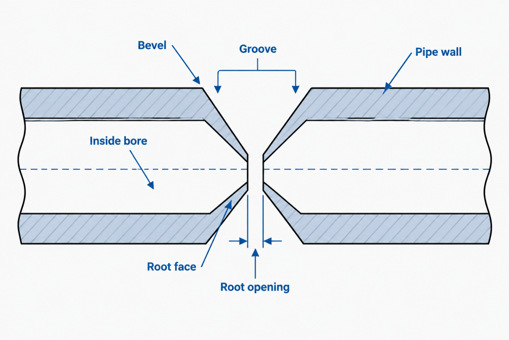
End preparation is the geometry and surface condition created at the end of a pipe or fitting before welding. For a typical butt-welded connection, the relevant terms can include:
- Bevel: An angled surface machined or cut around the end of the component.
- Groove: The combined space formed by the prepared ends when the joint is assembled.
- Root face: The small, generally unbeveled portion remaining at the inside edge of a prepared end. It may also be called a land.
- Root opening: The separation between the component ends at the joint root before welding. In drafting conversations, this is often called the root gap.
- Included angle: The total angle formed by the opposing prepared surfaces.
- Internal mismatch: Misalignment between the inside surfaces of the joined components.
- Counterbore or transition: Local internal machining used when adjacent bores or wall thicknesses need a controlled transition.
These features influence welding access, fit-up, penetration, and the completed joint profile. They are not determined solely by nominal pipe size or schedule. Material, wall thickness, fabrication method, project specification, and the approved welding procedure may all affect the required preparation.
Why CAD Models Often Show a Zero-Gap Joint
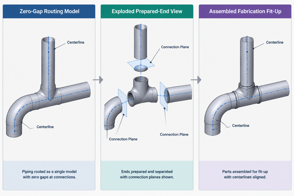
In many piping models, butt-weld components terminate at a shared connection plane. The pipe centerline remains continuous, and the adjacent solids appear to touch. This is a practical modeling convention rather than a statement that fabrication must use a zero root opening.
The shared plane provides a stable basis for routing and dimensioning. It also supports automated connectivity, component placement, isometric generation, and material reporting. If every modeled joint included a physical assembly gap, overall routing dimensions could become harder to manage and software connection rules might interpret the components as disconnected.
A zero-gap model can therefore represent a welded joint accurately at the design level, provided the project defines how fabrication allowances are handled. The model shows where the connection occurs; the fabrication documents explain how the ends are prepared and assembled.
Connection Plane, Cut Plane, and Fit-Up Position
Three different geometric ideas may exist at one weld, and they should not be treated as interchangeable.
| Geometry | What it represents | Typical use |
|---|---|---|
| Connection plane | The nominal interface between connected piping items | Model connectivity, routing, and design dimensions |
| Cut plane | The physical end of the pipe after cutting and preparation | Shop cutting, machining, and spool fabrication |
| Fit-up position | The assembled location of the prepared ends before welding | Joint alignment and root-opening control |
Depending on the project workflow, the connection plane may coincide with one of the cut planes, fall between two prepared ends, or remain a purely nominal reference. A spool drawing should avoid forcing the shop to infer this relationship from a schematic weld symbol or a magnified CAD view.
How Root Gaps Affect Pipe Cut Lengths
A pipe length measured between nominal component connection points is not automatically the saw-cut length. The fabrication length may need to account for end preparation, fit-up spacing, fitting takeout, machining, and the shop’s established cutting convention.
This does not mean designers should manually subtract a root gap from every model segment. Doing so can introduce inconsistent geometry, especially when automated isometrics and spool systems already apply fabrication rules. Instead, the project should define a single source of truth for cut-length calculation.
A reliable workflow answers these questions:
- Does the reported pipe length represent nominal design length or actual cut length?
- Does the fabrication system apply end-preparation allowances automatically?
- Are allowances assigned by weld type, component type, or shop procedure?
- Can a drafter override a calculated value, and is that override traceable?
- How are field-fit pieces distinguished from fixed shop-cut pieces?
If the software produces only nominal lengths, the spool package should identify that limitation. If it produces adjusted cut lengths, reviewers should verify the rule configuration rather than repeating the adjustment in drawing notes.
Choosing the Right Level of CAD Detail
Process and Layout Models
At the layout level, a butt weld usually needs connectivity, a weld location, and correct component geometry. Modeling the physical bevel or root opening adds little coordination value and can burden the model with small faces and fragile constraints.
Fabrication Isometrics and Spool Drawings
Fabrication documents need more explicit control. They should identify weld locations, component limits, pipe-piece marks, and the meaning of reported lengths. A standard joint detail or reference note may define end preparation without drawing every bevel at full scale.
Special Joint Details
Detailed geometry is more useful when a connection differs from the project’s normal joint practice. Examples include unequal wall transitions, counterbored ends, special backing arrangements, proprietary component ends, or joints requiring a controlled internal profile. These conditions should be detailed intentionally and coordinated with engineering and fabrication.
When Not to Draw a Bevel
A bevel shown in CAD can look authoritative even when it is only symbolic. Avoid adding realistic end geometry merely for visual effect. Once a bevel appears on a fabrication detail, readers may reasonably assume that its angle, root face, and relationship to the bore are controlled.

Do not derive bevel geometry from a generic block when the governing welding information is unknown. Likewise, do not scale a small schematic symbol to obtain fabrication dimensions. If a drawing needs to communicate the presence of a prepared end without controlling its exact geometry, use a clear note or symbolic detail and direct fabrication to the governing approved documentation.
Where the Controlling Information Should Come From
Pipe dimension tables are valuable for identifying outside diameter and nominal wall information, but they do not by themselves define an acceptable weld preparation. The controlling inputs may include the project piping specification, welding procedure, fabrication specification, component manufacturer’s end details, and engineering requirements for a particular joint.
CAD should carry or reference approved information rather than inventing it. When sources disagree, the discrepancy should be resolved before issuing the drawing. The drafter should not select a preparation based only on what fits neatly in the model.
A Practical Drafting Workflow
- Identify the joint type. Confirm whether the connection is a butt weld, socket weld, branch weld, attachment weld, or another configuration.
- Establish the nominal connection location. Keep the routing model tied to a stable connection plane and centerline system.
- Determine the document level. Decide whether the deliverable is for layout, coordination, spool fabrication, field installation, or a special joint detail.
- Find the governing fabrication information. Check the approved project and welding documents rather than assuming a generic preparation.
- Confirm the length convention. Verify whether reported lengths are nominal, cut, or adjusted by fabrication software.
- Add only necessary detail. Use standard references for routine joints and enlarged details for exceptions.
- Review automated output. Check that weld IDs, piece marks, dimensions, and bills of material remain consistent after any joint-specific change.
- Record exceptions clearly. Flag special machining, transitions, or field-prepared ends where the normal fabrication rule does not apply.
Common Documentation Errors
- Dimensioning to a drawn bevel tip: Small graphical changes can shift the apparent endpoint and create an unreliable measurement basis.
- Showing a root gap in the model without defining its purpose: Reviewers may interpret it as a clash, a broken connection, or a mandatory fabrication value.
- Subtracting allowances twice: A manual pipe-length adjustment may duplicate an automatic fabrication rule.
- Using nominal wall data as finished-end geometry: Actual end preparation may involve machining or transitions not represented by the nominal pipe body.
- Applying one detail to every butt weld: Component ends and special joint conditions may require different treatment.
- Letting visual detail outrank written control: A realistic-looking model is not a substitute for approved welding information.
Review Checklist for Weld-End Documentation
- Is the nominal weld location unambiguous?
- Are dimensions taken from stable connection or centerline references?
- Does the drawing explain whether pipe-piece lengths are nominal or fabrication cut lengths?
- Are special end preparations separated from routine joints?
- Do enlarged details agree with component bore and wall information?
- Has any automatic end allowance been checked for duplicate manual adjustment?
- Are field-prepared and shop-prepared ends distinguishable where necessary?
- Does the drawing reference the correct controlling project documentation without attempting to replace it?
Keep Design Geometry and Welding Control Separate
The most reliable piping CAD workflow uses simple, stable geometry for routing while giving fabrication enough information to prepare and fit the real joint. A shared connection plane can be appropriate in the model even though the physical ends will be beveled and separated during fit-up.
The key is not to model every microscopic feature. It is to define what each dimension means, identify where fabrication requirements are controlled, and prevent nominal model lengths from being mistaken for shop cut lengths. That separation makes the CAD model easier to coordinate and the fabrication package easier to trust.
How to Apply This Guidance During Drawing Review
Review the model and the fabrication output as related but separate records. The model establishes routing, connectivity, and nominal component locations. The fabrication package must communicate how pipe pieces are measured, prepared, identified, and assembled.
When a length discrepancy appears, first determine the reference points behind each value. One dimension may run between nominal connection planes, while another may represent a physical cut length after the fabrication system applies its configured allowances. Comparing the numbers without comparing their definitions can lead to an unnecessary correction.
Information That Should Remain Traceable
- Length basis: State whether a reported pipe-piece length is nominal, calculated for fabrication, or intentionally left for field fitting.
- Preparation authority: Identify the approved project, welding, fabrication, or manufacturer information that governs the prepared end.
- Software treatment: Document whether allowances are generated automatically, entered manually, or handled outside the CAD system.
- Exceptions: Make special machining, bore transitions, and nonstandard component ends visible to reviewers and fabricators.
- Revision impact: Recheck piece marks, weld records, dimensions, and material output whenever a joint rule or endpoint changes.
A Useful Handoff Principle
A drafter should not expect the shop to measure a bevel from a model image, and a fabricator should not have to guess whether a model-space gap is intentional. Stable nominal references should control layout, while approved fabrication information controls the real end preparation. The drawing connects those systems by defining terminology, length conventions, and exceptions.
Frequently Asked Questions
Does a zero-gap CAD connection require the pipe ends to touch during welding?
No. A shared connection plane commonly represents nominal connectivity. The required fit-up position and root opening come from the governing fabrication and welding information, not from the apparent contact between model solids.
Should a root gap be subtracted from every modeled pipe length?
Not automatically. The correct treatment depends on the project’s length convention and on whether fabrication software already applies an allowance. Manual subtraction can duplicate an existing rule and produce an incorrect cut length.
Can a modeled bevel be used as a fabrication dimension?
Only when the geometry is intentionally controlled, dimensioned, and coordinated with the approved fabrication information. A symbolic or visually realistic bevel should not be scaled to determine machining or cutting requirements.
Why can the nominal pipe length differ from the shop cut length?
The dimensions may use different endpoints or account for different operations. End preparation, fit-up treatment, fitting takeout, machining, and the configured shop workflow can affect the physical cut length.
Where should routine weld preparation be documented?
Routine preparation is often best handled through approved project or fabrication documentation referenced by the drawing. Enlarged CAD details are more useful for exceptions, transitions, proprietary ends, or other joints that differ from normal practice.
What should be checked when CAD and spool output report different lengths?
Compare the reference planes, endpoint definitions, allowance settings, component takeout, manual overrides, and field-fit status. Resolve which output represents nominal geometry and which represents the intended fabrication value before revising either record.