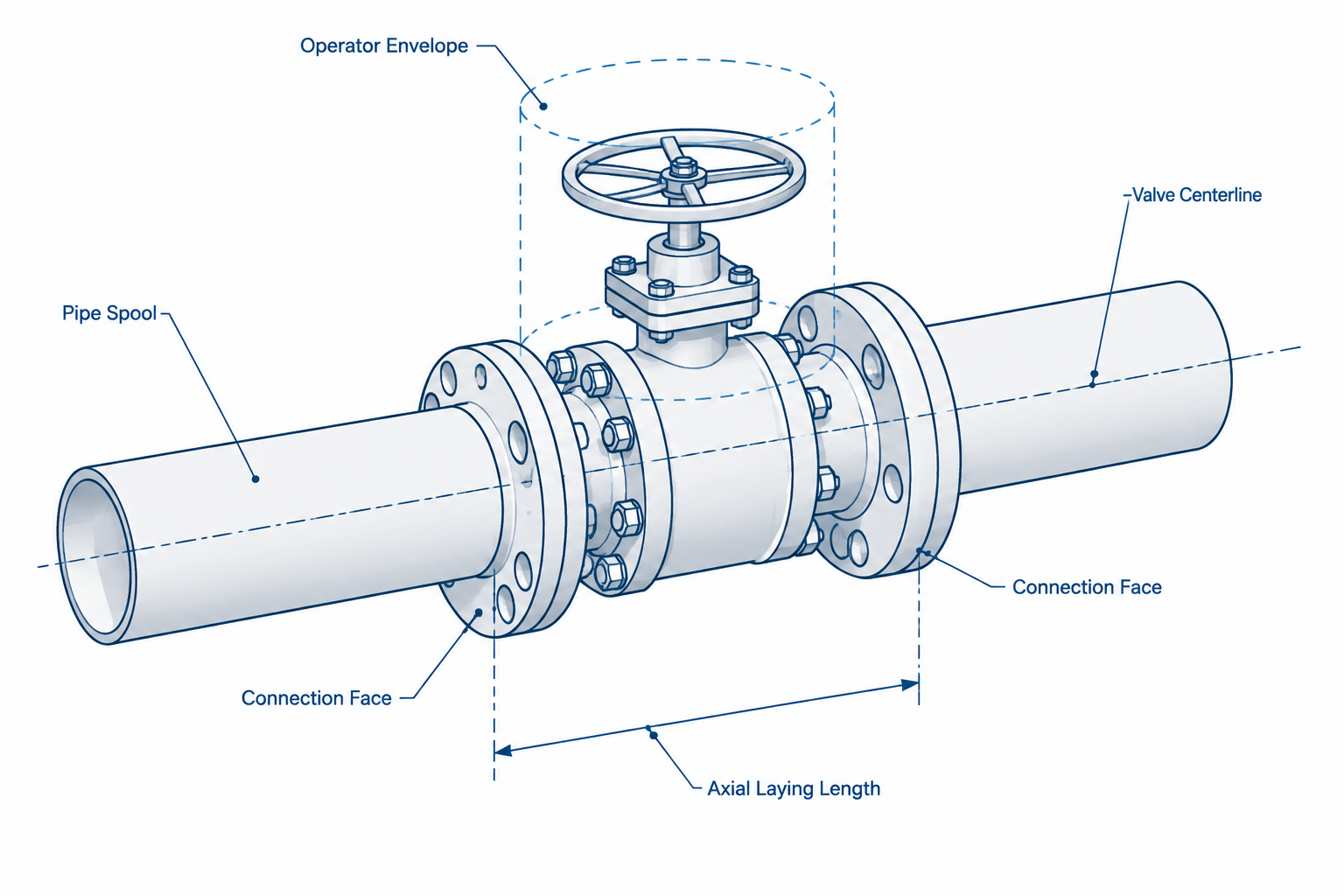
Valve face-to-face dimensions in CAD connect component selection with the physical geometry of a piping system. They help designers establish connection planes, control spool lengths, evaluate replacement valves, and identify layout changes before fabrication or installation.
Use this guide when reviewing a preliminary valve model, coordinating vendor data, replacing an installed valve, or investigating why a selected component does not fit between existing connections. The central question is not merely whether two valves share a description, but whether their documented interfaces and operating envelopes are compatible with the same piping arrangement.
A valve may have the correct size, pressure class, material, and end connection yet still be the wrong length for an existing piping layout. The controlling measurement is often the valve face-to-face dimension: the distance occupied by the valve between its connecting faces.
This dimension affects flange locations, adjacent pipe cut lengths, support positions, equipment clearances, and whether a replacement valve can be installed without modifying the surrounding piping. For CAD users, it is therefore more than a catalog value. It is a layout-control dimension that should be verified and tracked throughout design, procurement, and construction.
What Is a Valve Face-to-Face Dimension?
For a flanged in-line valve, face-to-face generally describes the axial distance between the two mating flange faces of the valve. It defines how much space the valve body occupies along the piping centerline, excluding the separate mating flanges and their joint components.
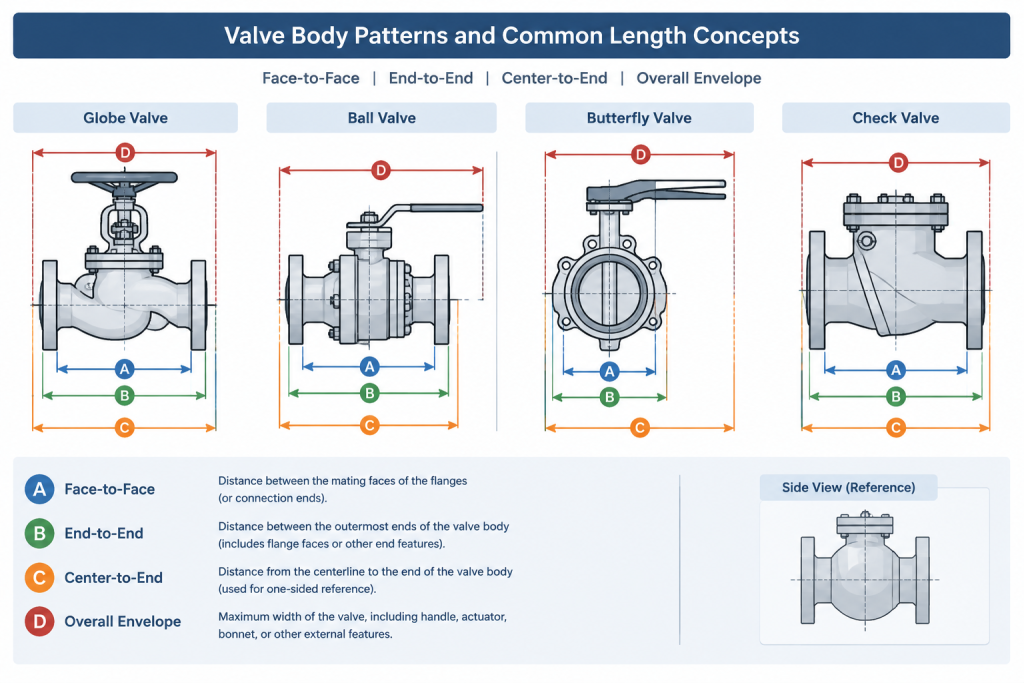
The term is most straightforward for straight-pattern flanged valves, but related measurements may be used for other configurations:
- End-to-end: A broader term commonly applied to valves with welding, threaded, socket, or other end preparations.
- Center-to-end: Often needed for angle-pattern valves or components where the inlet and outlet are not on one straight axis.
- Laying length: A general description of the installed axial length between connection points. Its exact interpretation should be confirmed for the component involved.
- Overall length: A potentially ambiguous catalog term that may include projections not relevant to the pipe connection planes.
These terms should not be treated as automatically interchangeable. A vendor drawing should show the measurement endpoints clearly enough to identify the actual connection planes.
Why Valves with Similar Descriptions Can Have Different Lengths
Valve face-to-face dimensions may be associated with standardized dimensional series, but a basic valve description does not always identify the applicable series. Length can depend on the valve type, body pattern, end configuration, pressure class, construction, and manufacturer design.
For example, two valves described by the same nominal pipe size may differ because one is a gate valve and the other is a ball valve. Even two valves of the same general type may use different body constructions or dimensional series. Compact, regular-pattern, reduced-port, full-port, wafer, lug, and specialty designs can occupy different amounts of piping space.
Do not select a CAD length from nominal size alone. At minimum, verify:
- Valve type and body pattern
- Nominal pipe size or DN designation
- Pressure class or other applicable rating designation
- End connection type and facing
- Port configuration where it affects construction
- Applicable dimensional standard or vendor series
- Selected manufacturer and model when procurement is sufficiently developed
A dimensional standard can narrow the possibilities, but it does not replace confirmation that the purchased valve follows the intended series.
Face-to-Face Is Not the Complete Valve Envelope
Face-to-face controls the valve’s axial installation length, but it does not describe the full space required for operation and maintenance. A CAD model also may need to account for the handwheel, lever, gearbox, actuator, stem travel, body width, drain features, and removable internals.
| Dimension or envelope | Primary use in CAD | Common risk if omitted |
|---|---|---|
| Face-to-face or end-to-end | Sets connection planes and adjacent spool lengths | Flanges or weld ends do not align |
| Body width and height | Checks structural and piping clearance | Body clashes with steel, walls, or nearby lines |
| Operator envelope | Checks access and operating movement | Handwheel, lever, or actuator cannot be used |
| Removal envelope | Reserves space for maintenance | Valve or internal parts cannot be withdrawn |
| Weight and center of gravity | Supports handling and support coordination | Inadequate support or impractical removal planning |
A placeholder valve model can be acceptable during early routing, but the drawing or model status should make clear which dimensions remain unverified.
How Face-to-Face Controls the Piping Layout
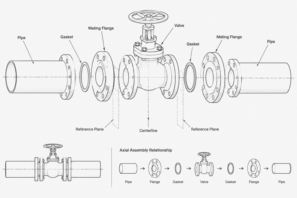
In a flanged assembly, the valve lies between two mating flange faces. The complete assembly length also involves the flanges, gasket interfaces, and adjacent pipe or fitting geometry. Changing the valve length while holding both surrounding pipe runs fixed creates a dimensional conflict.
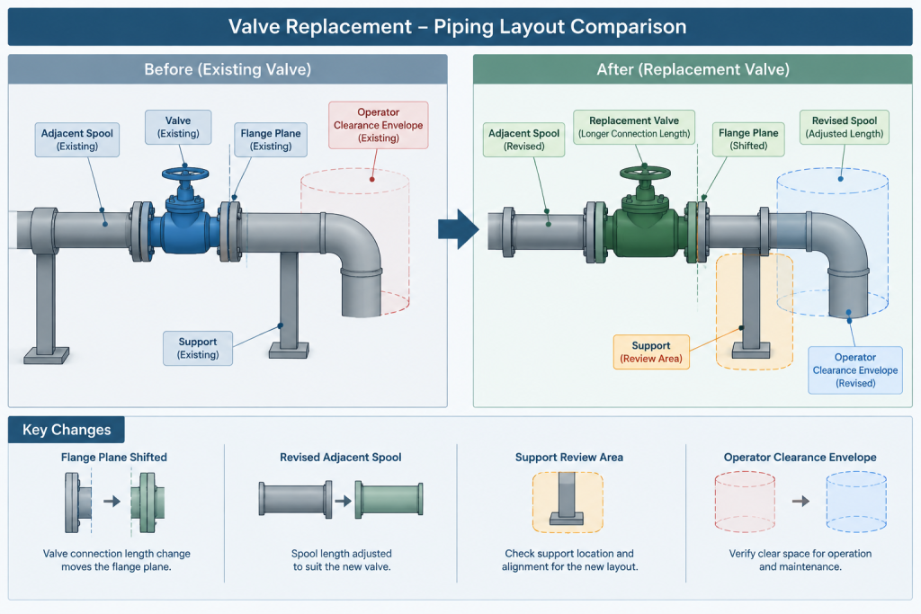
Possible consequences include:
- Moving one or both mating flanges
- Changing a neighboring pipe cut length
- Revising a prefabricated spool
- Relocating a support or guide
- Shifting an operator into a clearance conflict
- Changing equipment nozzle loads or fit-up conditions
- Revising isometric dimensions and material takeoffs
This is why a valve should not be replaced in the model by stretching a generic block until it fits. That approach may preserve the visible gap while concealing an unverified component selection.
A Practical CAD Verification Workflow
1. Establish the connection planes
Locate the actual mating faces or end points in the CAD model. Do not measure to flange edges, body edges, insulation outlines, or schematic symbols. The model ports should coincide with the physical connection planes represented by the supplier data.
2. Record the source and status
Identify whether the length comes from a preliminary standard-based assumption, a project component catalog, a supplier catalog, or an approved vendor drawing. A verified value and a routing allowance should not look equally authoritative in the model.
3. Check the complete valve identity
Compare the modeled item with the line specification, valve list, P&ID, and procurement description. Confirm that the valve type, size, rating designation, material requirements, ends, and operator arrangement refer to the same component.
4. Compare model geometry with vendor data
Measure between the modeled ports and compare that result with the documented face-to-face or end-to-end dimension. Also verify that the vendor dimension uses the same endpoints. A matching number is not sufficient if one drawing measures between flange faces and another measures to a different reference plane.
5. Review connected geometry
After updating the valve, check both adjoining connections. Confirm flange alignment, gasket location, bolt access, weld locations where applicable, spool dimensions, and nearby fittings. A small change at the valve can propagate into several fabrication dimensions.
6. Check operation and removal
Review the operator orientation, access route, lifting path, and maintenance envelope. Replacement planning should consider how the valve will pass between fixed flanges and whether the piping system provides enough controlled separation for removal.
7. Update downstream documents
Synchronize the model, isometric, bill of materials, valve schedule, and procurement references. If a vendor change alters the valve length, the revision should reach every document that controls fabrication or installation.
Replacement and Interchangeability Checks
Matching face-to-face dimensions can make a replacement easier, but dimensional equality alone does not establish interchangeability. The replacement also must be evaluated for end compatibility, rating, material, bore or port arrangement, flow direction, operating characteristics, actuator needs, and project requirements.
When replacing an existing valve, create a comparison record containing the old and proposed component information. Useful fields include:
- Connection-to-connection length
- Connection type and facing
- Body and operator envelope
- Stem or actuator orientation
- Available removal space
- Adjacent flange condition and alignment
- Support arrangement
- Need for a revised spool or adapter
Existing drawings should not be assumed to represent the installed condition exactly. Field verification may be necessary, especially where the piping has been modified, forced into alignment, or assembled with nonstandard transition pieces.
Common Drafting Mistakes
- Using one generic valve length for every class or type: Similar symbols do not imply identical physical dimensions.
- Scaling a CAD block: Scaling can distort flange geometry, operator size, and port locations without creating a valid component.
- Measuring to the body outline: The body casting is not necessarily the connection reference.
- Ignoring gasket interfaces: The valve face-to-face dimension and total joint stack are related but different checks.
- Assuming a standard series without recording it: Later users may not know whether the model reflects a verified product or a design placeholder.
- Updating the model but not the isometric: Fabrication documents can retain obsolete spool dimensions.
Recommended Model Data
A reliable valve object should separate geometry from identifying data. Useful properties include valve tag, line number, component type, size, rating designation, end connection, dimensional series, face-to-face value, manufacturer or model when selected, data source, and verification status.
This information makes replacement safer and helps reviewers distinguish between a geometrically accurate valve and a preliminary routing object. The goal is not to overload every drawing with notes, but to preserve enough traceable data that the connection length can be checked before fabrication.
Final Review Principle
Treat valve face-to-face dimensions as controlled interface data. Verify the measurement endpoints, connect the value to a specific component description, and review the effect on surrounding piping whenever the valve selection changes. A valve that fits the specification but not the available space can still require costly spool revisions, field fit-up, or layout changes.
Applying the Information During Design Reviews
A face-to-face check should be treated as an interface review rather than an isolated catalog lookup. The controlling data must agree across the valve description, CAD object, connected piping, fabrication documents, and procurement record. If any source refers to a different body pattern, end arrangement, or dimensional series, the apparent match requires further investigation.
Separate routing assumptions from approved geometry
Preliminary models often use representative components so routing can proceed before a manufacturer is selected. That is a reasonable workflow when the assumed geometry is clearly identified. Once supplier information becomes available, replace or validate the placeholder and review every connected item affected by the valve connection planes.
Use a focused change-control checklist
- Identity: Confirm that the model and documentation describe the same valve type, ends, body pattern, rating designation, and operator arrangement.
- Reference planes: Confirm that the CAD ports and supplier dimensions use the same physical endpoints.
- Connected piping: Recheck mating flanges, adjoining spool geometry, nearby fittings, supports, and access.
- Document consistency: Review isometrics, valve schedules, material records, and procurement descriptions after a dimensional change.
- Status: Record whether the geometry is assumed, catalog-based, supplier-confirmed, or field-verified.
Distinguish a candidate replacement from an interchangeable valve
A matching connection length identifies a possible replacement candidate, not an automatically interchangeable component. Engineering review must also address connection compatibility, service requirements, flow characteristics, operator needs, access, maintenance space, and the condition of the existing installation.
For retrofit work, compare vendor information with field conditions whenever practical. The installed gap, flange alignment, support arrangement, and available removal path may not match legacy drawings. Capturing those conditions before purchase reduces the risk of discovering a fit-up conflict during an outage or installation activity.
Valve Face-to-Face Dimension FAQ
Can valves with the same nominal size be assumed to have the same face-to-face dimension?
No. Nominal size alone does not establish valve length. Valve type, body pattern, end configuration, rating designation, dimensional series, and manufacturer design may affect the required connection-to-connection distance.
Does a face-to-face dimension include the mating pipe flanges?
For a flanged in-line valve, the dimension generally refers to the distance between the valve’s mating faces. Separate mating flanges and joint components are part of the surrounding assembly and should be checked independently.
Is a matching face-to-face dimension enough to approve a replacement?
No. It confirms only one aspect of dimensional compatibility. The review must also consider the ends, facing, valve function, bore or port arrangement, operator, material requirements, service conditions, maintenance envelope, and project specifications.
Where should CAD ports be placed on a flanged valve model?
The ports should coincide with the physical mating-face planes identified by the applicable component data. Body edges, flange outside edges, insulation outlines, and symbolic insertion points are not substitutes for verified connection planes.
Can a generic valve block be stretched to match the available space?
Stretching a block may make the graphics appear to fit, but it does not verify that a real valve has the represented geometry. Use a controlled placeholder with an explicit status, then update it from applicable supplier or project data.
What should be reviewed after a valve length changes?
Review both adjoining connections, spool geometry, flange alignment, supports, operator access, maintenance clearance, isometric dimensions, material records, and procurement documents. The effect may extend beyond the valve itself.
When is field verification important?
Field verification is particularly important for replacement work when existing drawings may not reflect modifications, forced alignment, unusual transition pieces, or the actual space available for removal and installation.