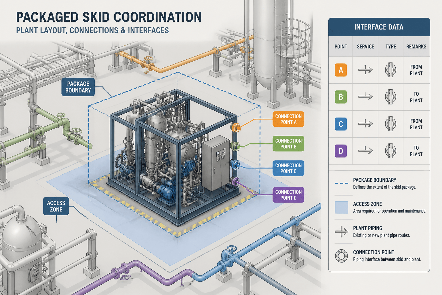
Vendor equipment rarely arrives as a perfectly complete and final CAD object. Supplier information may develop while plant piping is being routed, reviewed, and revised. That makes the interface between the package and the surrounding design a controlled coordination point rather than just a modeling task.
This guide explains how to show package boundaries, connection data, responsibility, and revision status so reviewers can distinguish confirmed information from planning geometry. The goal is a model that supports routing and multidisciplinary review without giving preliminary vendor data more authority than it has earned.
Vendor packages create a special coordination problem in piping design. A pump skid, compressor package, heat exchanger assembly, filtration unit, or packaged utility system may be designed outside the main plant model, yet its connections must fit the surrounding piping. The piping CAD model therefore needs to show enough package information for layout and coordination without pretending that incomplete or preliminary vendor data is final.
A clear interface representation separates three things: the physical boundary of the package, the information required to connect to it, and the party responsible for confirming that information. When these items are mixed together, designers can route from the wrong nozzle, model temporary geometry as permanent, or miss a change issued by the vendor.
What a vendor package interface means
A vendor package interface is the documented connection between equipment or piping designed by a supplier and the surrounding plant design. The interface may include process nozzles, utility connections, electrical or instrument connections, drains, vents, structural attachment points, access zones, and maintenance envelopes.
In a piping model, the interface is usually represented by a combination of:
- A package boundary or battery-limit line
- Equipment or skid outline geometry
- Nozzle locations and orientations
- Connection sizes, end types, and service identifiers
- Reference elevations and coordinates
- Access, removal, and maintenance space
- A source, status, and revision for each important item of data
The package boundary is not necessarily a physical wall. It is often a design and responsibility boundary. It tells the project team where vendor-supplied geometry ends and the plant piping model begins.
Why package boundaries matter in CAD
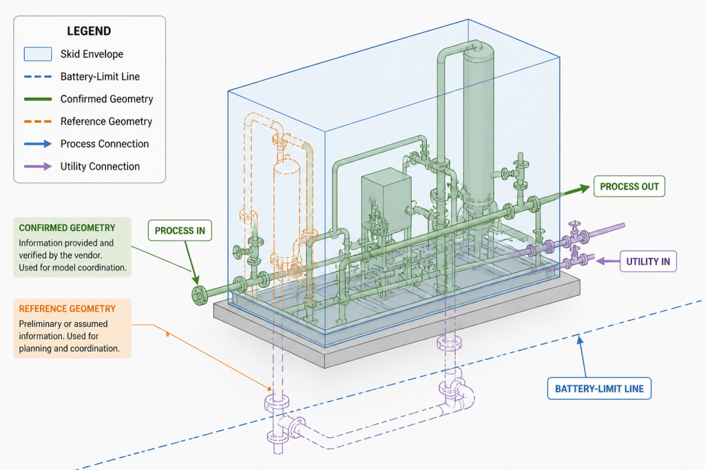
Without an explicit boundary, a model can give the impression that all geometry has the same design status. A detailed-looking skid may be mistaken for approved supplier geometry even when it is only a preliminary envelope. Conversely, a simplified package block may hide a nozzle, valve, instrument, or access zone that affects routing.
Use the boundary to distinguish between:
| Model information | Purpose | Typical review question |
|---|---|---|
| Package envelope | Shows the space occupied by the supplied equipment | Does the surrounding layout reserve enough physical space? |
| Interface connection | Defines where plant piping connects | Is the route connected to the correct service and nozzle? |
| Reference geometry | Supports coordination without claiming fabrication status | Is this geometry confirmed, estimated, or for planning only? |
| Ownership boundary | Identifies who develops and verifies each item | Who must confirm a changed dimension or orientation? |
Use model layers, object properties, colors, or drawing notes according to the project CAD standard. The important principle is consistency: the visual treatment should make the package status understandable in both the model and extracted drawings.
Start with an interface register
Before detailed routing, create or review an interface register. This can be a project database, spreadsheet, model property set, or controlled drawing schedule. Its purpose is to give every interface a traceable identity instead of relying on an isolated nozzle callout.
Useful fields include:
- Package or equipment identifier
- Connection or nozzle identifier
- Service or line reference
- Nominal connection size and connection type, when confirmed
- Orientation and location reference
- Design status, such as preliminary, for coordination, or approved
- Source document or supplier communication reference
- Revision and date received
- Responsible organization for confirmation
- Open comments, assumptions, or required actions
This register should not replace the governing line list, piping specification, equipment data sheet, or approved supplier document. It provides a coordination layer that connects those sources to the CAD model.
Represent the package at the right level of detail
Detail should follow the coordination need. A package model that is too simple may conceal clashes and maintenance problems. A model that is too detailed can consume time, slow revisions, and create false confidence in unverified information.
Use an envelope model for early layout
An envelope model may include the overall package outline, major equipment masses, connection zones, lifting or removal space, and known access areas. It is suitable when supplier geometry is incomplete or when the project is comparing layout options.
Use connection-level detail for routing
Once piping is routed, the model should show each relevant connection with its correct identity, location reference, orientation, and end condition when available. A generic cylinder or unlabelled port is not enough if several connections are close together or serve different systems.
Use detailed vendor geometry selectively
Detailed flanges, valves, instruments, supports, and internal equipment geometry should be included when they affect clearance, access, fabrication, operation, or clash review. Keep nonessential details out of the main coordination model if they do not influence those decisions.
Document nozzle and connection data clearly
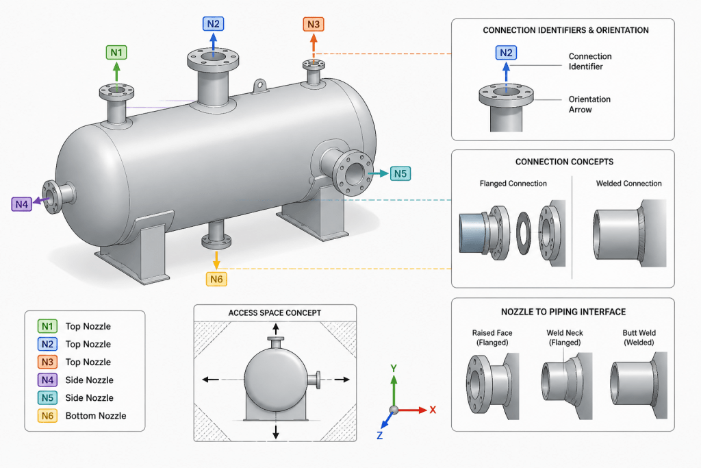
Connections are often the most important part of a vendor package interface. A piping route can appear correct in plan view while connecting to the wrong port, approaching from the wrong direction, or requiring an unplanned offset.
For each connection, check the following:
- The connection identifier matches the supplier information and the project line reference.
- The modeled location uses the agreed coordinate and elevation reference.
- The orientation is shown relative to the package or plant coordinate system.
- The connection type is compatible with the intended mating component.
- The route leaves enough space for bolting, welding, insulation, access, and removal where applicable.
- The connection is classified as confirmed or provisional.
- Any temporary spool, transition piece, or field adjustment is identified rather than hidden in the model.
Do not infer missing nozzle information from a visually similar package or from a generic catalog model. If the supplier has not confirmed a location or orientation, mark the item as an assumption and record the action needed to close it.
Show data ownership and status in the model
Package coordination becomes difficult when geometry status is visible only in email or meeting notes. Carry status into the CAD environment through object properties, layer conventions, revision notes, or a dedicated interface schedule.
A practical status system may distinguish between:
- Reference: included to support layout but not yet suitable for final routing decisions
- Coordinated: reviewed between the vendor and plant design teams for the current purpose
- Approved: released through the project’s document-control process
- Superseded: retained for history but not valid for current coordination
Use the project’s actual status terminology where one exists. Avoid presenting a preliminary vendor model with the same graphical weight or metadata as approved plant design information.
Coordinate revisions without losing the interface history
Vendor revisions can change connection positions, package dimensions, access zones, and support requirements. A revised model should be compared with the previous accepted interface, not simply inserted over it.
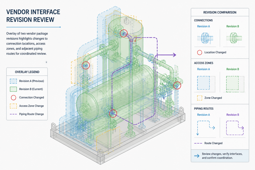
During a revision review, compare:
- Package origin and overall envelope
- Connection identifiers and service assignments
- Nozzle locations and orientations
- Required access and removal zones
- Structural or support contact points
- Insulation, heat tracing, or special clearance assumptions
- Changes to adjacent piping, supports, platforms, and walkways
Record whether each change requires rerouting, a drawing revision, a new clash review, an updated bill of material, or confirmation from another discipline. Keeping the old interface data as a controlled comparison can reveal changes that are not obvious in a single overlay.
Review the surrounding piping, not only the package
A package interface is successful only when the connected plant design also works. Review the first section of connected piping for alignment, flexibility needs, support strategy, valve operation, drainability, insulation, and access. Then review the broader route for clashes and constructability.
Pay particular attention to locations where the vendor package controls the geometry. These may include short, rigid connections, closely spaced nozzles, piping routed beneath removable equipment, and connections that pass through a package frame or structural member.
Practical checklist for package interface review
- Is the package boundary visible and consistently identified?
- Is the model status clear to reviewers?
- Does every connected line use the correct interface identifier?
- Are confirmed data and assumptions distinguishable?
- Have connection orientation and reference coordinates been checked?
- Are access, removal, and maintenance zones represented?
- Have supplier revisions been compared with the previously coordinated data?
- Are open interface actions assigned to a responsible party?
- Do drawings and schedules use the same current interface data?
- Has the surrounding piping been reviewed after the latest package change?
Conclusion
Vendor package coordination in CAD is more than inserting a supplier model into a plant layout. It is the disciplined representation of a boundary, a set of connections, and a chain of information ownership. A good interface model shows what is known, what is assumed, who controls each item, and how changes will be checked.
When package envelopes, connection data, status, and revision history are handled consistently, piping designers can route with greater confidence while avoiding unnecessary detail. The result is a CAD model that supports coordination without overstating the authority of preliminary vendor information.
How to use this page during design reviews
Read the package interface as a chain of evidence. The package envelope explains where the supplied equipment occupies space. The interface register identifies the connections and their source information. The CAD representation communicates how that information is currently being used. Together, these elements help reviewers ask the right question at the right level.
Separate geometry from design authority
A detailed model can be visually persuasive even when its dimensions or connection locations remain provisional. Conversely, a simplified block can be useful for early layout if its limitations are clearly marked. The key distinction is not how realistic the model looks, but whether its status and intended use are obvious.
Treat each nozzle as a controlled interface
Nozzle coordination should connect the supplier identifier, plant line reference, service, location, orientation, and connection information. If any of those items is unresolved, record the uncertainty instead of allowing the CAD model to imply certainty. This is especially important where nearby connections look similar or where a route has little freedom to adjust.
Make responsibility visible
Data ownership does not mean that one organization owns every decision. It means that the model identifies who provides, checks, accepts, or updates each interface item. Clear responsibility reduces the risk that a changed vendor dimension remains unnoticed because it was treated as a plant-design assumption.
Use revision review as a design check
When a supplier revision arrives, compare its interface consequences with the currently coordinated model. Look beyond the package outline: a small change to a connection, support point, access zone, or removal path can affect routing, supports, platforms, insulation, operations, and drawing deliverables. Preserve the comparison record so reviewers can understand what changed and why follow-up work is required.
Common coordination mistakes to avoid
- Routing from an unverified port because it appears in a detailed-looking model.
- Hiding a temporary spool or field adjustment inside generic geometry.
- Using color alone to communicate status without supporting metadata or notes.
- Replacing an earlier interface file without retaining a controlled revision comparison.
- Checking the package in isolation while overlooking connected piping, access, supports, or maintenance needs.
These mistakes are usually information-management problems expressed through CAD. A consistent boundary convention, interface register, status method, and revision workflow can prevent them before they become routing or construction issues.
Frequently asked questions
What should a vendor package boundary show?
It should show the extent of the supplied package and identify where vendor-controlled information meets the surrounding plant design. It may also identify connection zones, access areas, removal space, and other coordination limits when those affect layout.
Is a vendor package boundary always a physical line?
No. It is often a design and responsibility boundary rather than a wall or enclosure. Its purpose is to clarify which information belongs to the supplier package and which information is developed in the plant model.
How should provisional nozzle information appear in CAD?
Show it with the project’s approved reference or preliminary status convention and connect it to an assumption or open action. Do not present an unconfirmed location or orientation with the same authority as released design information.
What information belongs in an interface register?
The register commonly identifies the package, connection, service, location reference, orientation, connection information, status, source, revision, responsible organization, and unresolved actions. It should support—not replace—the governing project documents.
When is detailed vendor geometry necessary?
Include detail when it affects routing, clearance, access, fabrication, operation, supports, removal, or clash review. Omit nonessential detail from the main coordination model when it adds visual complexity without supporting a design decision.
Why compare a revised vendor model with the previous model?
Overlay or compare revisions to identify changes that may be difficult to notice in the latest model alone. The review should consider connections, envelope, access, supports, adjacent piping, and other affected disciplines, then assign the required follow-up actions.