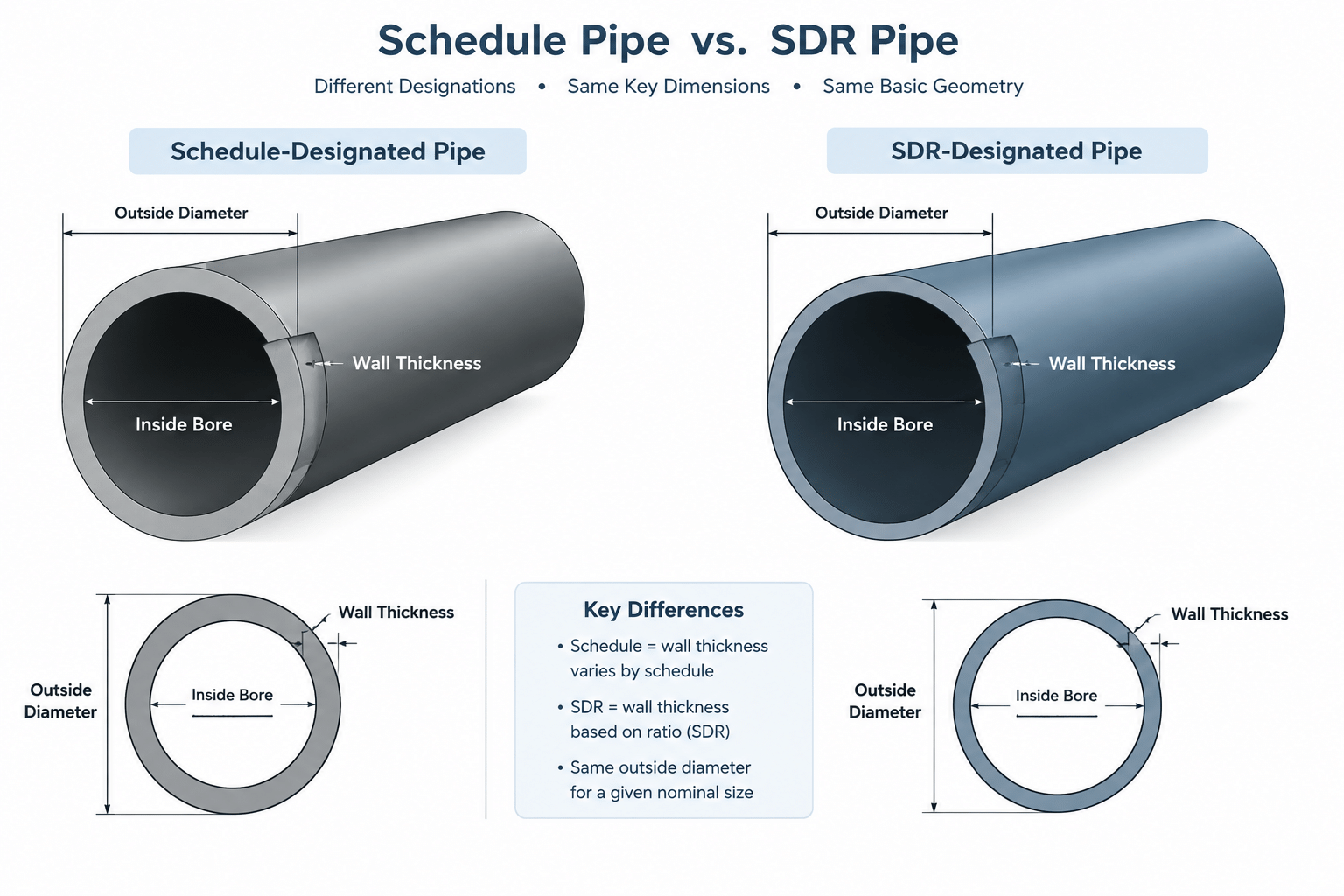
Pipe schedule vs. SDR is not a comparison between equivalent labels. Schedule identifies a wall series that must be resolved through dimensional data for the selected nominal pipe size. SDR expresses the relationship between outside diameter and wall thickness within an applicable pipe product series.
Understanding that difference helps prevent incorrect bore calculations, mismatched CAD components, unsuitable transition details, and incomplete material descriptions. The controlling dimensions should always come from the governing specification, approved project data, or verified manufacturer information.
Pipe schedule and standard dimension ratio (SDR) are both used to classify pipe wall thickness, but they do not describe it in the same way. A schedule is a designation tied to tabulated dimensions for a particular nominal pipe size and product standard. SDR is a ratio between pipe outside diameter and wall thickness.
This distinction matters when reading specifications, selecting CAD components, calculating pipe bore, or coordinating systems made from different materials. Treating a schedule number as an SDR value—or assuming that similarly labeled pipes have interchangeable dimensions—can produce incorrect inside diameters, connection geometry, and material descriptions.
What Pipe Schedule Means
Pipe schedule is a standardized wall-thickness designation commonly encountered with metallic piping and some nonmetallic pipe products. The schedule label identifies a wall series, but it is not itself a physical dimension.
For a given nominal pipe size, the applicable dimensional table provides the actual outside diameter and nominal wall thickness. The same schedule applied to another nominal size usually produces a different wall thickness. There is no general formula that converts a schedule designation directly into inches or millimeters.
Several practical consequences follow:
- The schedule must be interpreted together with the nominal pipe size.
- Actual wall thickness must come from the governing dimensional or product standard.
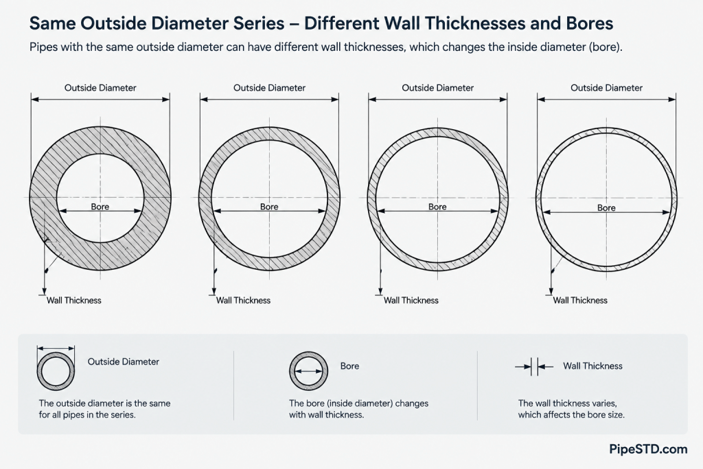
- Pipe inside diameter changes when the wall thickness changes while outside diameter remains fixed within the applicable size series.
- A schedule designation alone does not identify material, manufacturing method, corrosion allowance, or pressure capability.
A complete piping description therefore normally needs more information than size and schedule. Material specification, grade or class where applicable, end preparation, joining method, and project piping class may also control the component.
What SDR Means
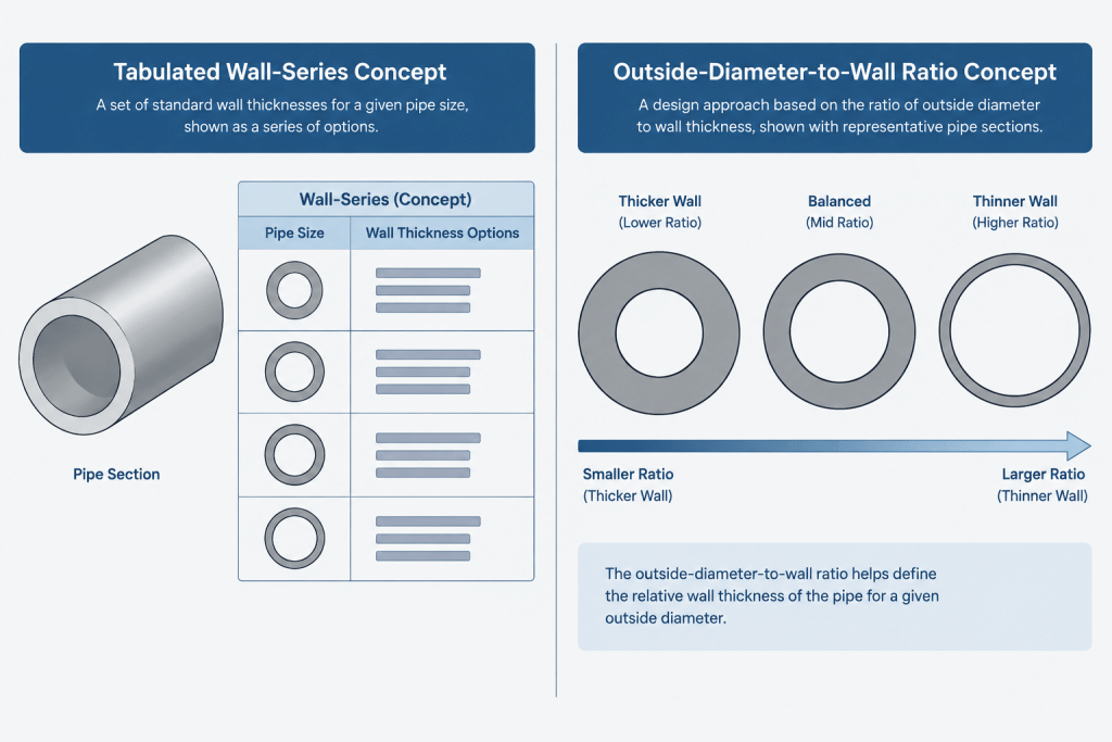
SDR describes the dimensional relationship between a pipe’s nominal outside diameter and nominal wall thickness. In simplified form:
SDR = outside diameter divided by wall thickness
Because wall thickness is the denominator, a lower SDR identifies a thicker wall relative to the outside diameter, while a higher SDR identifies a thinner wall relative to that diameter. This comparison is meaningful only when the pipes belong to the relevant product and outside-diameter system.
SDR is widely associated with thermoplastic piping, although ratio-based wall designations also appear in other pipe product families. The actual dimensions must still be taken from the applicable product standard or verified manufacturer data. Nominal dimensions, minimum-wall requirements, tolerances, and rounding practices cannot safely be reconstructed from the ratio alone.
Within one established outside-diameter series, the same SDR maintains a consistent nominal diameter-to-wall relationship as pipe size changes. That is fundamentally different from a schedule series, where the relationship between outside diameter and wall thickness is not represented by one constant ratio across all nominal sizes.
Pipe Schedule vs. SDR at a Glance
| Topic | Pipe schedule | SDR |
|---|---|---|
| Basic meaning | A designation linked to tabulated wall thicknesses | A ratio of outside diameter to wall thickness |
| Direct wall calculation | The label is not a wall-thickness formula | The ratio expresses a dimensional relationship, subject to the product standard |
| Behavior across sizes | Wall thickness is read separately for each nominal size | The same ratio is maintained within the applicable dimensional series |
| Common association | Frequently used for metallic piping and certain other pipe products | Frequently used for thermoplastic pipe products |
| Pressure information | Not a complete pressure rating by itself | Not a complete pressure rating by itself |
| CAD requirement | Size and schedule must resolve to verified OD and wall data | OD series and SDR must resolve to verified OD and wall data |
Why Neither Designation Is a Pressure Rating
A thicker wall can contribute to greater pressure capacity, but wall classification is only one part of the engineering evaluation. Pressure capability also depends on material properties, design temperature, manufacturing requirements, design factors, joining method, service conditions, and the governing code or product standard.
It is therefore unsafe to label every pipe of one schedule or SDR with a universal pressure value. Two products with similar geometry may use different materials or qualification bases. Fittings, valves, flanges, mechanical joints, and transitions may also impose limits below those of the straight pipe.
CAD designers should carry the approved dimensional designation without converting it into an assumed pressure class. Any pressure-related metadata should come from controlled engineering documents or verified product information.
Outside Diameter Systems Still Matter
SDR does not establish a universal outside diameter. A pipe must also belong to a defined dimensional series. Products described using nominal pipe terminology, metric nominal terminology, or tube-based sizing can have different outside diameters even when their trade-size labels appear similar.
This is especially important at material transitions. A metal pipe identified by nominal pipe size may not connect directly to a plastic pipe merely because both carry a similar nominal label. The designer must verify:
- Actual outside diameter on both sides
- Actual or nominal bore as required for the design
- End-connection type
- Fitting or adapter geometry
- Joint restraint requirements
- Allowable pressure and temperature limits
- Installation and joining requirements
A reducer is not automatically the correct solution. The transition may require a purpose-designed adapter, flange arrangement, mechanical coupling, or other approved assembly.
How Schedule and SDR Affect Inside Diameter
Pipe bore is derived from outside diameter and wall thickness. When a pipe size retains the same outside diameter but receives a thicker wall, its inside diameter becomes smaller.
This can affect flow calculations, velocity, pressure loss, cleaning access, instrument insertion, and bore alignment at connected components. A CAD model built only from nominal centerlines and outside-diameter cylinders may conceal these differences.
Full bore modeling is not necessary on every project, but bore-sensitive interfaces deserve special attention. Examples include transitions between wall series, lined components, branch intersections, internal probes, piggable systems, and butt-weld connections where an internal mismatch may require engineering or fabrication review.
Recommended CAD Data Structure
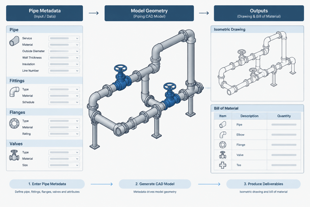
A reliable component record should keep source designations separate from calculated or resolved geometry. Useful fields include:
- Nominal size designation
- Dimensional system or outside-diameter series
- Schedule or SDR designation
- Verified outside diameter
- Verified nominal wall thickness
- Derived inside diameter, if needed
- Material specification and grade
- End connection
- Source document or catalog reference
- Revision or verification status
Do not use one generic field called “class” for schedule, SDR, pressure class, and material class. These terms serve different purposes. Separate properties make schedules, bills of material, and automated checks much easier to audit.
Model Geometry from Verified Dimensions
For routing models, the outside diameter usually controls clearance, insulation envelopes, supports, penetrations, and clashes. Wall thickness controls bore when the model or analysis requires it. Both values should resolve from approved dimensional data rather than from a designer’s interpretation of the designation.
If the model uses simplified solid cylinders, preserve the wall designation as component metadata. Otherwise, a visually correct pipe can still generate an incomplete or incorrect bill of material.
Keep Native Designations on Deliverables
Do not casually translate an SDR into the “nearest” schedule or replace a schedule with a calculated SDR. Even when two products have similar walls, their dimensional tolerances, materials, joining systems, and product requirements may differ.
Drawings and material lists should retain the designation required by the piping specification. Supplemental inch or metric dimensions may be shown where useful, but the controlling product description should remain clear.
A Practical Review Workflow
- Identify the pipe product. Confirm the material family, governing specification, and dimensional series.
- Read the native wall designation. Determine whether the source uses schedule, SDR, or another wall series.
- Resolve actual dimensions. Obtain outside diameter and wall thickness from controlled reference data.
- Check connected components. Verify fittings, valves, flanges, adapters, and equipment nozzles independently.
- Review the bore where relevant. Look for internal steps, restrictions, lining conflicts, or insertion problems.
- Check the model properties. Confirm that size, wall designation, material, and end connection remain distinct fields.
- Verify the output. Compare the isometric and bill of material with the piping specification and approved component data.
Key Takeaway
Pipe schedule is a tabulated wall-series designation; SDR is an outside-diameter-to-wall-thickness ratio. Neither one is a complete description of the pipe, and neither should be treated as a universal pressure rating. Accurate CAD and documentation require the nominal size, dimensional series, verified outside diameter, verified wall thickness, material, and connection requirements to be considered together.
How to Interpret Wall Designations in Practice
Begin with the complete pipe description rather than the wall label alone. Identify the pipe product, material specification, nominal size system, dimensional series, wall designation, and connection method. These details establish which dimensional reference applies and whether the selected fittings and joining components belong to the same system.
A schedule entry should be treated as a lookup designation. An SDR entry should be treated as a ratio-based designation associated with a defined product series. Neither approach eliminates the need to verify published outside diameter, wall thickness, tolerances, and connection requirements.
Common Coordination Errors
- Comparing labels instead of dimensions: Similar-looking designations do not establish equivalent outside diameters, walls, bores, or joining requirements.
- Using nominal size as measured diameter: A nominal label identifies a size category and should not be substituted for verified geometry.
- Converting between systems without product data: A calculated geometric similarity does not make a schedule pipe interchangeable with an SDR pipe.
- Assigning pressure capability from wall designation: Pressure suitability requires material, temperature, joint, product, and design-code information in addition to wall geometry.
- Modeling only the external cylinder: A visually plausible model can still contain incorrect wall metadata, bore geometry, or material descriptions.
Specification and CAD Review Questions
Before approving a component or transition, confirm that the dimensional source matches the specified product family. Check whether the outside diameter controls support and clearance geometry, whether the bore affects process or mechanical requirements, and whether an approved adapter is required between unlike systems.
For CAD libraries, keep the native schedule or SDR designation in a dedicated property. Store resolved outside diameter and wall thickness separately, with traceable source and revision information. This structure supports clearer bills of material and reduces the risk of treating calculated geometry as the controlling product description.
Frequently Asked Questions
Can pipe schedule be converted directly to SDR?
Not as a universal conversion. A schedule must first be resolved to the verified outside diameter and wall thickness for the applicable nominal size and product standard. A geometric ratio could then be calculated for comparison, but it would not replace the pipe’s native schedule designation or make it an SDR product.
Does a lower SDR mean a thicker pipe wall?
Within the same applicable outside-diameter series, a lower SDR indicates a thicker wall relative to the outside diameter. Actual dimensions and permitted tolerances must still be obtained from the relevant product data.
Does a higher schedule always mean a higher pressure rating?
No. A thicker wall may contribute to pressure capacity, but schedule alone is not a pressure rating. Material properties, temperature, manufacturing requirements, joints, fittings, service conditions, and the governing design basis also matter.
Why can schedule pipe and SDR pipe have different connection geometry?
They may belong to different outside-diameter systems, material families, fitting systems, and joining methods. Similar nominal labels do not prove that the outside surfaces, bores, or end connections will align.
Which dimensions should be used in a piping CAD model?
Use verified outside diameter for external geometry and clearance work. Use verified wall thickness or inside diameter where bore geometry matters. Preserve the native schedule or SDR designation, material, dimensional series, and end connection as separate component properties.
Can an SDR value be used to reconstruct a purchase specification?
No. SDR alone does not identify the complete pipe product. Procurement and engineering descriptions also require the applicable size series, material requirements, product specification, joining details, and other project-controlled information.