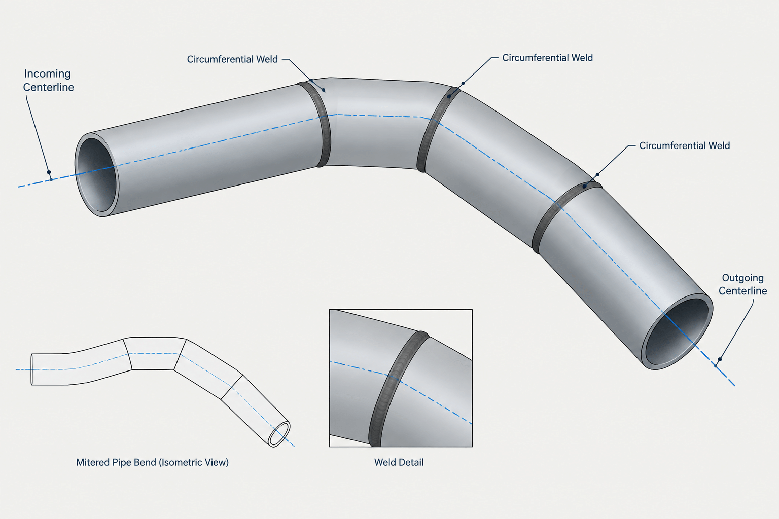
Mitered pipe bends in CAD require more than a convincing change in routing direction. The model must represent a fabricated assembly whose segment axes, angled joint planes, weld locations, and end interfaces remain consistent from design through shop documentation.
The reference below focuses on the information needed to distinguish design intent from fabrication data. It is intended to help piping designers, drafters, reviewers, and fabricators recognize which geometry controls the route, which details define the pieces, and which production decisions still require an approved engineering or shop procedure.
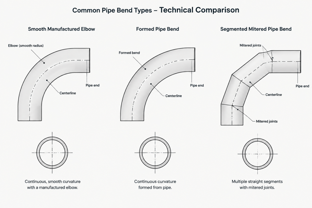
A mitered pipe bend changes direction by joining straight pipe segments cut at angles. Unlike a manufactured elbow or a smoothly formed pipe bend, its change in direction is distributed across one or more welded miter joints. This construction can be useful where project specifications permit fabrication from pipe, but it requires more documentation than simply placing an elbow symbol in a model.
For a piping designer or drafter, the main challenge is not drawing an angled line. The challenge is communicating the intended centerline path, segment arrangement, cut geometry, weld locations, and overall envelope without implying unsupported fabrication details. A visually convincing CAD model may still be incomplete if a fabricator cannot identify the controlling dimensions.
This guide explains the practical geometry and documentation issues involved in mitered pipe bends in CAD. Acceptance, pressure design, reinforcement, examination, and fabrication requirements must always be confirmed against the governing design basis, piping specification, and approved fabrication procedures.
What Is a Mitered Pipe Bend?
A mitered bend is assembled from pipe pieces whose angled ends form a directional change when welded together. The individual pieces are commonly described as segments or gores. A bend may contain a single miter joint or several joints that divide the total change in direction into smaller increments.
The following terms should not be treated as interchangeable:
- Manufactured elbow: A fitting with standardized or manufacturer-defined dimensions and a continuously curved flow path.
- Formed pipe bend: A length of pipe bent to a specified centerline radius, generally without intermediate circumferential miter welds.
- Mitered bend: An assembly of angled pipe segments connected by welds.
- Miter joint: One angled joint between adjacent segments. A complete bend can contain more than one miter joint.
This distinction affects material reporting, weld identification, inspection planning, hydraulic review, and CAD component selection. A generic elbow block should not be used if it hides the fact that the item is a fabricated segmented assembly.
The Geometry That Controls the Assembly
Total Direction Change
Begin with the angle between the incoming and outgoing pipe centerlines. This is the required total direction change. In a symmetrical segmented bend, that change is divided among the joints. In an asymmetrical assembly, the individual changes may differ because of space constraints or connection geometry.
Do not assume that every segment has an equal angle merely because the finished bend looks regular. The drawing or model data should make the intended distribution clear.
Centerline Path
The pipe centerline remains the most reliable reference for routing and interface control. Establish the incoming tangent, outgoing tangent, and intended turning region before modeling the physical pipe surfaces.
A segmented bend does not have a truly continuous centerline arc through the fabricated pieces. Designers may still use a reference arc or nominal centerline radius to control the overall envelope. If such a radius is shown, the drawing should identify it as a layout reference rather than implying that the pipe wall is smoothly bent to that radius.
Miter Cut and Joint Plane
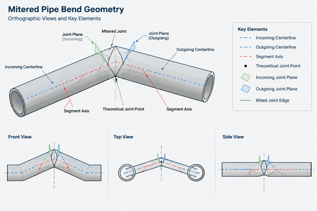
At each joint, the end of a round pipe is intersected by an angled plane. In a three-dimensional model, that intersection is not represented accurately by a simple square-ended cylinder rotated against another cylinder. The visible edge is an oblique intersection around the pipe circumference.
Each joint plane should be oriented so the adjoining segment centerlines meet as intended. For a symmetrical joint, the plane generally bisects the directional change between the two segment axes. Irregular arrangements require joint-by-joint control rather than a repeated generic cut.
Segment Length
Segment length can be ambiguous unless its reference points are identified. Possible interpretations include:
- centerline distance between adjacent joint planes;
- short-side length of a cut segment;
- long-side length of a cut segment;
- distance between theoretical joint centers;
- overall axial length measured along a selected generator of the pipe surface.
A dimension labeled only as segment length can therefore produce a fabrication error. Dimensions should identify the measurement path and endpoints, preferably with an enlarged detail when the joint geometry is crowded.
Single-Miter and Multi-Miter Arrangements
| Arrangement | Geometric Character | CAD and Drawing Concern |
|---|---|---|
| Single miter joint | The full change occurs at one joint | The sharp directional transition and joint plane must be explicit |
| Multiple equal segments | The change is distributed regularly | Repeated components can simplify modeling, but the controlling angle still requires verification |
| Multiple unequal segments | Joint angles or segment lengths vary | Each piece should be identified and dimensioned independently |
| Compound or nonplanar assembly | The route changes in more than one plane | Coordinates, rotations, and weld-plane orientations require three-dimensional checks |
Adding segments can make the centerline path approximate a smoother turn, but it also adds welds, fabrication operations, dimensional accumulation, and inspection points. Segment count should come from approved engineering and fabrication requirements, not from a drafter’s visual preference.
A Practical CAD Modeling Workflow
1. Establish the Connection Geometry
Place the incoming and outgoing pipe centerlines using verified coordinates, elevations, and directions. Confirm the available envelope and the locations of nearby supports, structures, equipment, flanges, and maintenance zones.
2. Define the Bend as an Assembly
Determine whether the project treats the bend as a single fabricated item, a spool subassembly, or separate cut pipe pieces. This decision affects component tags, material takeoff, weld numbering, and drawing organization.
3. Lay Out the Segment Axes
Construct the axis of each segment before creating solids. Check that consecutive axes meet at the intended theoretical joint locations and that the final axis aligns with the downstream route. For nonplanar bends, verify the geometry in multiple orthographic views rather than relying on a single isometric view.
4. Create the Physical Pipe Geometry
Generate pipe bodies using the correct outside diameter and the project’s modeling convention for wall thickness. Cut the ends with the intended joint planes. If the model is schematic or centerline-only, attach enough metadata or notes to prevent users from mistaking it for fabrication-ready geometry.
5. Identify the Welds
Show each miter joint as a distinct weld location when weld tracking is required. Do not merge the entire assembly into an anonymous solid if doing so removes joint count or location information needed for fabrication and inspection.
6. Validate the Final Interfaces
Confirm that the inlet and outlet ends have the required orientation and connection type. Check overall end-to-end geometry independently from the internal segment dimensions. A small angular error at one joint can shift the downstream connection significantly.
What the Fabrication Drawing Should Communicate
A useful drawing should define the assembly without forcing the shop to scale geometry from the view. Depending on the project’s documentation practice, the required information may include:
- pipe size, wall designation, material specification, and applicable line or component class;
- total direction change and the orientation of the bend plane;
- number of pipe segments and miter joints;
- individual joint deflections where they are not otherwise unambiguous;
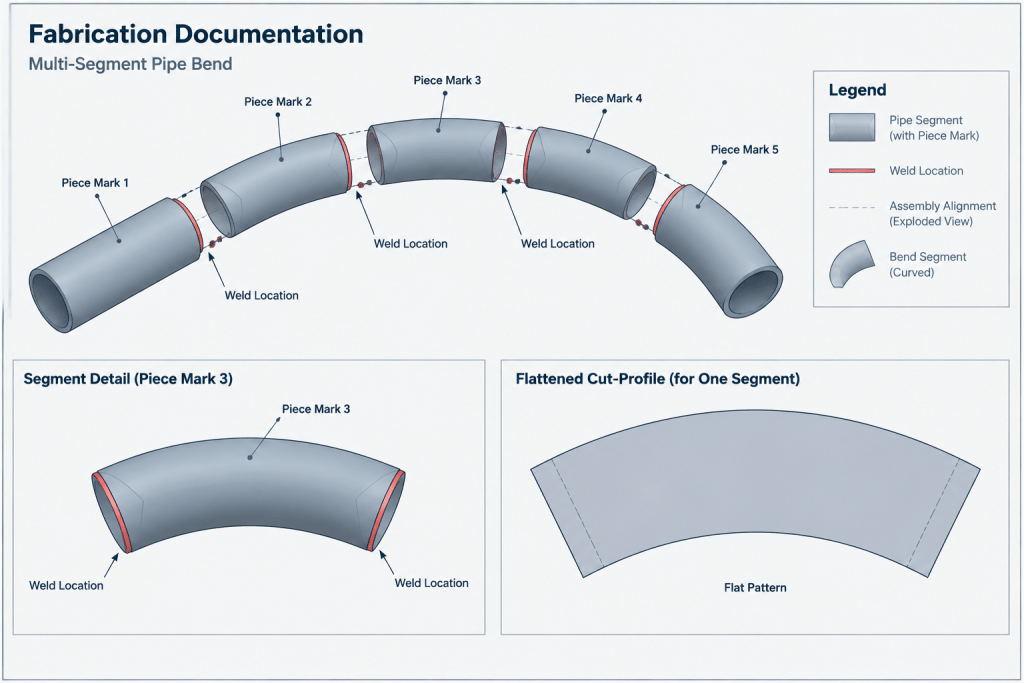
- segment identifiers tied to a cut list or bill of materials;
- controlling centerline dimensions and end coordinates;
- joint or weld identifiers;
- end preparation references from approved fabrication documentation;
- inlet and outlet connection types and rotational orientation;
- the distinction between theoretical layout points and physical cut edges.
A section or enlarged joint view can clarify the angled cut far better than dense dimensions on an isometric. For unequal segments, a piece-marked cut schedule may be clearer than trying to dimension every surface in the assembly view.
Developed Cut Patterns Are Separate Fabrication Data
The oblique end of a pipe produces a varying cut profile around its circumference. A developed pattern flattens that circumferential profile into a template or machine-readable cutting path. It is not the same thing as a side-view diagonal line.
Generating a reliable pattern requires the actual pipe geometry, cut-plane orientation, fabrication method, and any allowances used by the shop. Kerf, bevel preparation, fit-up practice, and trimming strategy can affect production information. A CAD drafter should not issue a developed template merely because the software can unfold or intersect solids. The output must follow the fabricator’s approved workflow and be checked at full scale or through an appropriate digital verification process.
Material Takeoff and Component Data
A mitered bend can be represented in a bill of materials in several ways. One project may list a fabricated bend as a single item, while another may list the individual pipe segments and associate them with a spool. Either approach can work if it remains consistent with procurement and fabrication responsibility.
Avoid reporting the assembly as a standard elbow unless that is genuinely how it is specified and supplied. Useful data fields can include the assembly identifier, segment piece marks, parent line number, material, wall designation, end connections, segment count, and fabrication status. Weld records should remain traceable to the physical joints even when the material list uses one assembly item.
Common CAD and Detailing Errors
- Using a smooth elbow solid: This conceals the segmented construction and intermediate welds.
- Dimensioning only the apparent radius: A reference radius does not fully define segment lengths or joint planes.
- Confusing joint deflection with cut angle: These are related geometric quantities but should not be labeled interchangeably.
- Using square pipe ends at angled joints: Overlapping or gapped cylinders do not represent the actual cut profile.
- Omitting the bend plane: An angle alone cannot define a three-dimensional directional change.
- Rounding dimensions independently: Separate rounding of angles and lengths can prevent the assembled outlet from reaching its required coordinate.
- Ignoring weld accessibility: A geometrically valid assembly may be difficult to weld or inspect when placed close to steel, equipment, or another fitting.
- Issuing unchecked cut templates: Model intersections are not automatically approved shop data.
Final Review Checklist
- Are the inlet and outlet centerlines based on verified interfaces?
- Is the assembly clearly identified as mitered rather than smoothly bent?
- Are segment count and joint locations visible and traceable?
- Do all axes, joint planes, and physical solids agree?
- Are dimensions tied to clearly defined points, planes, or centerlines?
- Does the outlet coordinate close correctly after all segments are assembled?
- Are welds accessible for the intended fabrication and examination workflow?
- Does the material representation match the project’s procurement responsibility?
- Have specification, design, and fabrication acceptance requirements been confirmed by the responsible disciplines?
Mitered pipe bends in CAD should be treated as fabricated assemblies, not as approximate substitutes for elbows. A dependable model begins with controlled centerline geometry and follows through to explicit segment, joint, weld, and interface information. When the drawing distinguishes layout references from physical cut geometry, it becomes easier for engineering, fabrication, inspection, and field teams to review the same design intent.
Managing the Model Through Design and Fabrication
A mitered bend model may serve several purposes during a project. Early routing geometry can establish the required envelope and connection directions, while a later fabrication model may contain separate segment bodies, joint planes, piece marks, and weld records. The model status should be clear so that preliminary geometry is not mistaken for approved shop information.
Separate Routing Control from Piece Geometry
The inlet and outlet centerlines, bend plane, and interface coordinates control how the assembly fits the piping system. Segment cuts and developed profiles control how individual pieces are produced. Keeping these information layers distinct makes revisions easier to review and helps prevent a routing adjustment from silently invalidating fabrication data.
Define Information Ownership
Project documentation should identify who is responsible for segment development, end preparation, cutting allowances, weld details, and final dimensional verification. Depending on the workflow, these items may be completed by piping engineering, detailing personnel, a spool fabricator, or a coordinated combination of disciplines. CAD capability alone does not establish approval authority.
Use Revision Checks That Follow the Assembly
When a connection point, direction, or available envelope changes, review the entire segmented assembly rather than moving only its outlet. Confirm the segment axes, joint planes, physical cut edges, weld identifiers, piece marks, material records, and downstream interface. A model can appear connected while its drawing views or cut information still reflect an earlier arrangement.
Coordinate Space Around the Bend
Clash detection should account for more than the outside surface of the finished pipe. Fabrication, welding, examination, coating, insulation, support installation, and field assembly may require access around the joints. These needs should be coordinated with the responsible disciplines rather than represented by unsupported generic clearances.
Drawing and Model Quality Checks
- Geometry check: Verify that centerlines, segment solids, and joint planes describe the same assembly.
- Interface check: Confirm end position, direction, connection type, and rotational orientation.
- Traceability check: Make sure piece marks, weld identifiers, and material records refer to recognizable physical items.
- View check: Use views that reveal the bend plane and any out-of-plane routing without relying on visual scaling.
- status check: State whether the information is conceptual, design-controlled, issued for fabrication, or supplied for reference under the project’s document system.
- approval check: Confirm that pressure design, fabrication, examination, and acceptance remain governed by the applicable project requirements.
The most useful CAD deliverable is not necessarily the most detailed solid. It is the deliverable that communicates its level of development, preserves the controlling interfaces, and allows every segment and joint to be checked against the approved design basis.
Frequently Asked Questions
Is a mitered pipe bend the same as a manufactured elbow?
No. A mitered bend is assembled from angled pipe segments joined by welds, while a manufactured elbow is a fitting with its own defined geometry. The distinction affects modeling, material reporting, weld tracking, and fabrication documentation.
Can a reference radius fully define a mitered bend?
No. A reference radius can help control the overall layout or envelope, but it does not by itself define the segment axes, joint planes, piece lengths, or cut profiles. The drawing should explain what the radius controls.
Are joint deflection and pipe cut angle interchangeable terms?
No. Joint deflection describes the directional change between adjoining segment axes. Cut angle describes the orientation used to form an end or joint plane. Related values should be labeled according to the geometry they actually represent.
Should every miter joint appear as a separate weld in CAD?
If the project requires weld identification, inspection traceability, or spool documentation, each physical joint should remain identifiable. A merged solid should not conceal weld count or location information needed by downstream users.
Can a CAD intersection be issued directly as a cutting template?
Not automatically. A geometric intersection may establish the theoretical profile, but production data can also depend on the approved cutting method, end preparation, allowances, fit-up practice, and verification procedure.
How should a nonplanar mitered bend be checked?
Review it in coordinated model views and verify the centerline directions, joint-plane orientations, end coordinates, and rotational relationships. A single isometric view may conceal an incorrect out-of-plane rotation.
Who determines whether a mitered bend is acceptable for service?
Acceptance must come from the responsible engineering and fabrication authorities using the governing design basis, piping specification, and approved procedures. The presence of complete CAD geometry does not establish design acceptance.