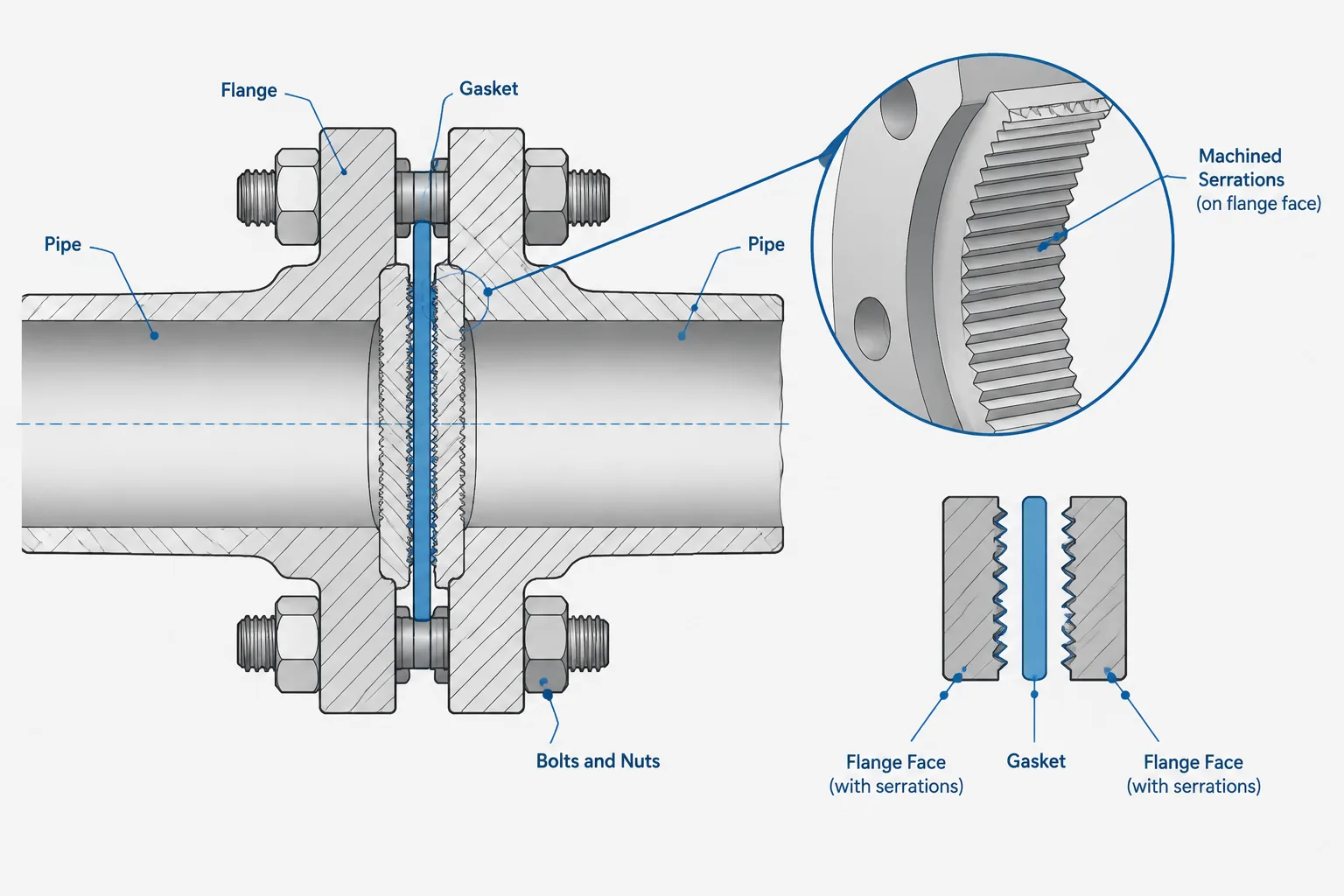
Flange facing finish defines the machined texture of the surface that contacts the gasket. In piping drawings and CAD systems, this requirement is normally communicated through controlled component data, specifications, or fabrication notes rather than by modeling every groove.
The practical challenge is keeping four separate concepts clear: flange face geometry, surface roughness, serration pattern, and gasket selection. This guide explains how those properties relate, where facing information should be documented, and what designers should verify at piping-to-equipment interfaces or existing flange connections.
A flange face is more than a flat surface at the end of a piping component. Its texture helps the gasket grip the joint, influences sealing behavior, and affects how the assembly responds during bolt-up and operation. For that reason, flange facing finish must be treated as a controlled technical requirement rather than a cosmetic modeling detail.
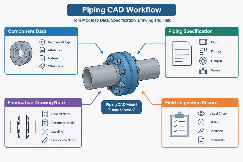
In CAD models, the actual grooves are rarely represented. Designers usually model the nominal flange geometry and communicate the required finish through specifications, component data, drawing notes, or fabrication details. The challenge is to identify where that information belongs and to avoid confusing surface finish with flange face type, gasket style, or general machining quality.
What Is Flange Facing Finish?
Flange facing finish describes the texture left on the gasket-contact surface after machining. Depending on the specified construction, the surface may contain visible tool marks arranged in a spiral-like path, a series of concentric grooves, or another controlled pattern.
The finish is commonly characterized by two related but separate properties:
- Surface roughness: A measurement-based description of the small peaks and valleys on the machined surface.
- Serration pattern: The physical arrangement of machining marks across the gasket-contact area.
A note that identifies only one property may not fully define the required surface. A roughness value alone does not necessarily communicate the groove pattern, while a pattern name alone may not establish the acceptable texture range. The controlling flange, gasket, manufacturer, and project documents must therefore be reviewed together.
Facing Finish Is Not the Same as Face Type
Face type describes the larger geometric form of the flange sealing area. Common examples include raised-face, flat-face, and ring-type-joint configurations. Facing finish describes the smaller-scale texture applied to a gasket-contact surface.
This distinction matters in both specifications and CAD libraries. A component labeled only as a raised-face flange does not automatically communicate every machining requirement. Likewise, assigning a surface-finish note does not change the modeled face from one geometric type to another.
| Property | What it describes | Typical documentation location |
|---|---|---|
| Face type | Nominal sealing-face geometry | Component description, piping class, model geometry |
| Facing finish | Texture of the gasket-contact surface | Specification, purchase description, fabrication note |
| Gasket type | Sealing element placed between mating faces | Piping class, joint definition, bill of material |
| Face condition | Actual cleanliness, damage, corrosion, or distortion | Inspection record, field report, repair documentation |
Common Serration Pattern Concepts
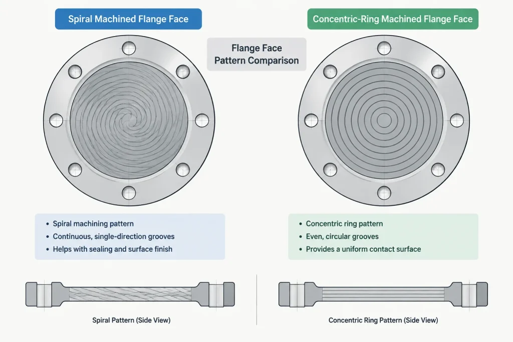
Spiral or phonographic pattern
A spiral pattern is produced by a machining path that progresses across the flange face. It may resemble the continuous groove of a phonograph record, which explains the informal term often used in shops and field discussions.
Because the tool path is continuous, its appearance differs from separately cut circular rings. The exact machining controls should come from the applicable purchasing and fabrication requirements rather than from a generic CAD note.
Concentric pattern
A concentric finish consists of circular grooves centered around the flange bore. These grooves are distinct rings rather than one continuous spiral path.
At ordinary drawing scales, spiral and concentric patterns may look nearly identical if represented literally. Text notation or an enlarged schematic detail is therefore more reliable than dense linework on a general arrangement drawing.
Smooth or specially controlled surfaces
Some joint designs require a smoother or otherwise specially controlled contact surface. However, “smooth” should not be used as an assumed universal description. A surface that looks polished may not meet the required measured finish, and a visibly grooved surface may still be correct for its intended gasket.
When a special finish is required, the drawing should point to the controlling requirement instead of relying on appearance-based terms such as smooth, rough, standard, or machine finish.
How Facing Finish Interacts with the Gasket
The flange face and gasket form a sealing system. Surface texture can help retain a gasket and provide local interaction between the gasket material and machined face. If the texture is inappropriate, the gasket may not seat or deform as intended.
Compatibility cannot be decided from flange geometry alone. The review should consider:
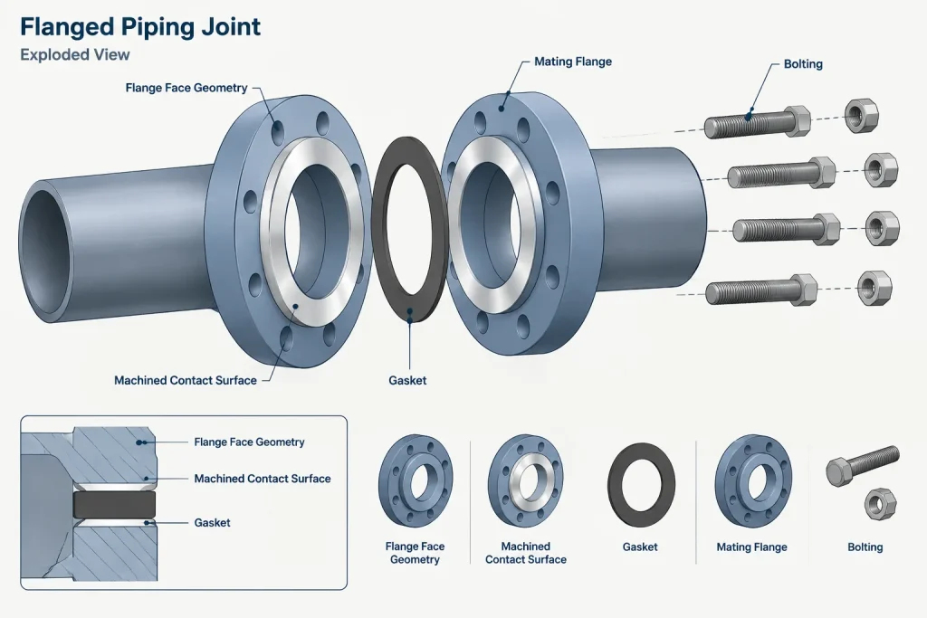
- Gasket construction and facing material
- Flange face type and available contact area
- Required surface finish and serration pattern
- Joint alignment and flange-face condition
- Assembly procedure and bolt-tightening controls
- Service conditions and piping specification requirements
A CAD designer should not select a facing finish merely because it is the library default. The piping material specification, gasket data, equipment requirements, and purchase documents may impose different controls.
What CAD Should and Should Not Model
Detailed serrations can create unnecessary geometry, large files, and distracting drawings. For most plant-layout models, the flange should show the geometry needed for envelope control, connection location, orientation, interference checking, and drawing production. Microscopic or closely spaced machining marks generally do not support those tasks.
Facing texture may need a graphic representation when preparing a fabrication detail, inspection aid, or explanatory section. Even then, the lines should be identified as schematic unless they are truly controlled geometry. A pattern drawn for clarity must not be mistaken for a machinable groove layout.
A practical representation strategy is:
- Model the correct face type and nominal joint location.
- Store the required finish as component or specification data where supported.
- Use a clear note on fabrication drawings when the requirement is not controlled elsewhere.
- Add an enlarged schematic only when it improves interpretation.
- Avoid modeling decorative grooves that imply unsupported manufacturing detail.
Documenting Facing Finish Without Creating Conflicts
Repeated technical requirements can drift out of agreement. If the same finish is entered independently in a piping class, flange data sheet, equipment drawing, isometric note, and purchase description, a later revision may update only some of those locations.
The project should establish one controlling source and use other documents to reference or extract that information. CAD output should not silently override the piping specification.
Before adding a finish callout, determine:
- Which document governs the flange and gasket combination?
- Whether the component is a standard catalog item or specially machined item
- Whether mating equipment flanges have vendor-specific requirements
- Whether the units and roughness convention are clearly identified
- Whether the note applies to one joint, one component type, or an entire piping class
Unit clarity is especially important because surface roughness may be expressed using different unit systems and parameter conventions. A bare number is not a complete finish callout.
Equipment Nozzles and Mixed-Source Joints
Joints between piping flanges and equipment nozzles deserve special attention. The piping flange may come from a project piping class, while the nozzle face is controlled by a vendor drawing or equipment specification. Matching nominal size and face type does not prove that every sealing detail is compatible.
The interface review should compare the face geometry, gasket selection, facing requirement, bore relationship, and any vendor restrictions. If the documents disagree, the issue should be resolved through the project’s technical review process rather than corrected informally in the model.
Existing Flanges and Field Verification
An existing flange cannot be fully evaluated from a legacy drawing or a nominal component tag. Corrosion, scratches, pitting, coating residue, previous machining, and mechanical damage may affect the usable sealing surface.
For brownfield work, drawings should distinguish between assumed design data and verified field condition. Photographs may support planning, but close visual inspection and appropriate measurement are often needed to determine whether a face is acceptable, requires repair, or must be replaced. CAD geometry should not be presented as proof of actual surface condition.
Practical Review Checklist
- Confirm that face type and facing finish are treated as separate properties.
- Verify the gasket against the controlling piping and equipment documents.
- Check that roughness notation includes the necessary parameter and unit context.
- Do not infer a finish solely from a flange’s visual appearance in CAD.
- Avoid unnecessary serration geometry in layout models.
- Review equipment-nozzle joints for requirements from different document owners.
- Identify the controlling source instead of repeating conflicting notes.
- Flag existing flange condition for field verification when it affects reuse.
Final Drafting Principle
Flange facing finish is a manufacturing and sealing requirement that is usually communicated as data rather than modeled as literal geometry. A reliable CAD workflow shows the correct flange face type, preserves the intended joint location, links the component to the governing specification, and adds detail only where it improves fabrication or inspection.
The most useful drawing is not the one with the most grooves shown. It is the one that clearly identifies which surface is controlled, what document governs it, and how the flange, gasket, and mating component form a compatible joint.
A Drawing-Control Workflow for Flange Facing Requirements
Facing information should move from the governing engineering requirement into purchasing, fabrication, inspection, and construction documents without being reinterpreted at each handoff. The CAD model can carry the appropriate component identity and face geometry, but it should not become an independent source of machining requirements unless the project has explicitly established it as one.
Identify the controlling requirement
Begin with the piping class, equipment documentation, gasket definition, purchase description, or other approved project source. If more than one document addresses the same flange face, confirm which source governs before adding a drawing note. Conflicting requirements should be resolved through technical review rather than combined into a new callout.
Define the scope of the callout
A useful note makes clear whether it applies to a particular gasket-contact surface, a selected joint, a component family, or a broader specification scope. Avoid placing a local note where readers could reasonably interpret it as applying to every flange on the drawing.
Separate required data from schematic graphics
An enlarged face illustration can help distinguish a continuous machining path from separate circular grooves, but the graphic should not replace the controlled finish requirement. If groove lines are illustrative, identify them as schematic so that their spacing and appearance are not treated as manufacturing geometry.
Check the document handoff
- Confirm that the flange face type matches the modeled and specified component.
- Confirm that the gasket definition belongs to the same joint.
- Ensure the finish notation includes the required parameter and unit context.
- Review vendor-controlled mating faces independently of the piping catalog.
- Keep inspection findings separate from nominal design requirements.
- Remove duplicate notes when they create competing sources of control.
Why Model Accuracy Alone Is Not Enough
A geometrically aligned pair of flanges can still have an unresolved sealing interface. CAD may confirm connection location, orientation, envelope, and mating face position, but it does not establish that the actual machined surfaces are undamaged or compatible with the selected gasket.
For that reason, model review, specification review, and physical inspection serve different purposes. A complete workflow uses each one for the information it can reliably provide instead of treating a visually correct model as proof of fabrication or field condition.
Frequently Asked Questions
Is flange facing finish the same as flange face type?
No. Face type describes the overall sealing-face geometry, while facing finish describes the machined texture on the gasket-contact surface. Both properties may need to be defined for the joint.
Should serrations be modeled in piping CAD?
Usually not in a plant-layout model. Literal grooves can add unnecessary complexity and may imply machining detail that the model does not control. A specification reference, component attribute, drawing note, or schematic detail is generally clearer.
Does a roughness callout fully define the serration pattern?
Not necessarily. Measured roughness and machining pattern describe related but different surface characteristics. The governing documents should establish whether both must be stated.
Can gasket compatibility be determined from flange geometry alone?
No. The review must also consider gasket construction, facing requirements, component documentation, assembly controls, service requirements, and the condition of the mating surfaces.
How should equipment nozzle flanges be reviewed?
Compare the piping requirements with the equipment vendor documentation. A matching nominal connection and face type do not by themselves confirm that the gasket and surface requirements agree.
Can an existing flange face be accepted from a legacy drawing?
A legacy drawing may indicate the intended design, but it cannot confirm present surface condition. Reuse decisions should account for field inspection, damage, corrosion, residue, previous machining, and the applicable project acceptance process.
What makes a flange finish note incomplete?
A callout may be incomplete if it omits the surface being controlled, the roughness parameter or unit context, the required pattern, its scope, or a clear reference to the governing requirement.