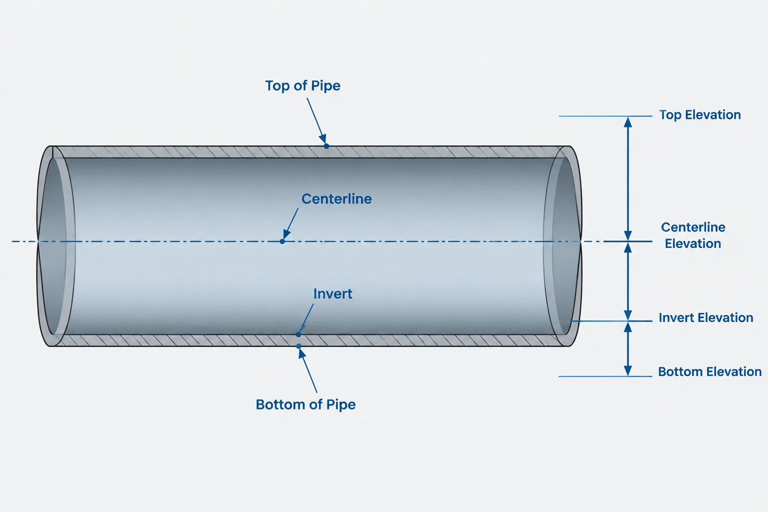
Pipe elevation notation in CAD must identify more than vertical position. It must also identify the exact pipe reference being located. Centerline, bottom of pipe, top of pipe, and invert describe different points on the same pipe section, so choosing the wrong reference can affect routing, drainage, clearance, and support coordination.
This guide explains how the common elevation references relate to pipe geometry, where each notation is typically useful, and what designers should verify when working with slopes, reducers, wall changes, insulation, components, and project datums.
Pipe elevation notation identifies the vertical position of a pipe, but not every elevation refers to the same part of the pipe. A centerline elevation, bottom-of-pipe elevation, top-of-pipe elevation, and invert elevation can all describe the same run from different reference points. Treating these terms as interchangeable can shift a modeled line, create false clearances, or produce conflicting construction dimensions.
The correct notation depends on why the elevation is being controlled. A piping designer may route pressure piping by centerline, while a drainage drawing may control the internal flow line. Structural coordination may focus on the outside bottom of the pipe, and clearance studies may need the outermost insulation or flange envelope. Clear drawings state both the elevation reference and the datum from which it is measured.
What a Pipe Elevation Actually Controls
An elevation is a vertical coordinate assigned to a defined point or surface. A note that gives only an elevation value is incomplete unless the drawing convention makes the reference point unmistakable. The reader needs to know whether the value applies to the pipe centerline, outside surface, internal flow line, support surface, or another feature.
Common pipe elevation notation includes:
- Centerline or CL: elevation of the pipe’s geometric axis.
- Bottom of pipe or BOP: elevation of the lowest outside surface of the bare pipe.
- Top of pipe or TOP: elevation of the highest outside surface of the bare pipe.
- Invert: elevation of the lowest internal surface of the flow passage.
- Bottom of insulation: elevation of the lowest point of the insulation or protective outer covering.
Project abbreviations vary. For example, a project may use different punctuation or word order for bottom-of-pipe notation. The abbreviation legend and project drafting standard should therefore govern the exact callout format.
Centerline Elevation
Centerline elevation is widely used for routing pressure piping because fittings, valves, branches, and equipment nozzles are commonly arranged around a shared axis. It provides a stable geometric reference for elbows and straight runs and is convenient for creating plans, sections, and isometric drawings.
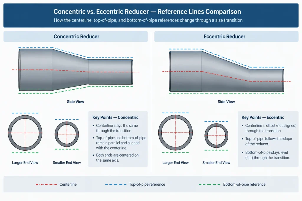
Centerline elevation is also useful when pipe outside diameter changes. A reducer can connect two centerlines concentrically, or it can maintain another controlled surface when installed eccentrically. The elevation notation should make that design intent clear rather than assuming every size transition preserves the same reference.
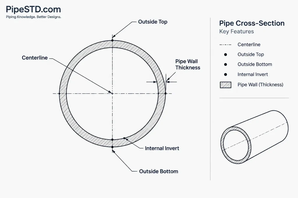
A centerline value alone does not define the actual lower clearance. The outside radius of the pipe, insulation, flange diameter, valve body, drains, supports, and other projections may extend below it.
Bottom-of-Pipe Elevation
Bottom-of-pipe elevation refers to the lowest outside surface of the bare pipe unless the drawing explicitly states otherwise. It is often useful when routing over structural steel, floors, equipment, cable trays, or other obstructions. A BOP control lets a designer maintain a consistent underside elevation even when connected pipe sizes change.
BOP should not automatically be interpreted as the bottom of insulation. An insulated line extends below the bare pipe surface, and weatherproofing, tracing, or removable covers may enlarge the envelope further. If clearance is critical, the drawing or model should distinguish bare-pipe BOP from the lowest outside extent of the complete assembly.
Bottom-of-pipe notation also requires care at fittings and components. The underside of a flange, valve body, strainer, or branch fitting may project below the cylindrical pipe surface. BOP is therefore a pipe reference, not proof that the entire line assembly clears an obstruction.
Top-of-Pipe Elevation
Top-of-pipe elevation identifies the highest outside surface of the bare pipe. It may be used where piping must remain below a platform, ceiling, overhead structure, duct, or other fixed boundary. Like BOP, it does not include insulation unless that condition is specifically stated.
TOP can be a useful control through eccentric reducers. For example, a layout may need to preserve the upper surface while the pipe size changes. The reducer orientation and the controlled elevation should agree in the CAD model, section views, and isometric information.
Designers should still evaluate local high points created by flanges, valve bodies, actuators, vents, and support hardware. Maintaining pipe TOP does not necessarily maintain the highest point of every component.
Invert Elevation
Invert elevation refers to the lowest internal surface of the pipe or conduit. It is especially important for gravity-flow systems because the internal flow path, rather than the outside pipe surface, controls drainage. Invert should not be used as a casual substitute for BOP.
The difference between invert and BOP is the pipe wall thickness. That distinction matters when wall thickness changes, even if the outside diameter remains unchanged. Linings, internal coatings, or other internal barriers may also affect the effective flow passage and should be handled according to the project definition.
For sloped gravity piping, invert elevations are tied to specific stations or endpoints. A single elevation cannot describe the complete run unless its location is identified. Drawings should make clear whether the value applies at a structure, fitting, equipment connection, grid line, penetration, or another defined point.
Relationships Between Elevation References
For a straight, circular, uninsulated pipe at a given section, the elevation references can be related geometrically. Using actual outside diameter and actual wall thickness:
- Centerline = BOP + outside diameter divided by two
- TOP = centerline + outside diameter divided by two
- Invert = BOP + wall thickness
These are geometric relationships, not substitutes for verified dimensional data. Nominal pipe size is not the outside diameter, and schedule is not itself a wall-thickness value. The applicable pipe dimension source and material specification must be checked before converting one elevation reference into another.
| Reference | Point being controlled | Typical use | Common coordination risk |
|---|---|---|---|
| Centerline | Pipe axis | Pressure-piping routing and nozzle alignment | Ignoring the physical envelope below or above the axis |
| BOP | Lowest bare-pipe outside surface | Clearance over steel, floors, and equipment | Confusing bare pipe with insulation or component envelope |
| TOP | Highest bare-pipe outside surface | Clearance below overhead obstructions | Missing flanges, valves, vents, or operators above the pipe |
| Invert | Lowest internal flow surface | Gravity drainage and underground flow paths | Using outside diameter without accounting for wall thickness |
How Size and Wall Changes Affect Elevations
A size transition can preserve the centerline, top, bottom, or another reference, but it generally cannot preserve all of them at once. With a concentric reducer, the connected pipe axes remain aligned while the outside top and bottom surfaces change. With an eccentric reducer, one selected outside surface may remain approximately aligned while the centerline shifts.
A wall-thickness change presents a different issue. Where two pipes share the same outside diameter but have different walls, their centerline, BOP, and TOP can remain aligned while their internal surfaces differ. The invert may therefore step even though the outside model appears continuous. This is particularly relevant when internal drainage geometry or bore continuity matters.
Sloped Pipe Requires a Location with Every Elevation
Horizontal piping may have one constant centerline or BOP elevation across a straight run. Sloped piping does not. Any elevation assigned to a sloped line belongs to a particular station along that line.
Useful reference locations include equipment nozzles, fitting center points, tangent points, branch intersections, building grids, support lines, penetrations, and tie-in points. Avoid placing an elevation leader where its exact attachment point is unclear. The slope direction, controlling endpoints, and elevation reference should work together without creating an overconstrained dimension chain.
In a three-dimensional model, verify whether the software reports the elevation of a component port, centerline node, endpoint, or selected surface. A displayed coordinate can be mathematically correct but still refer to the wrong physical feature.
Insulation, Linings, and Component Envelopes
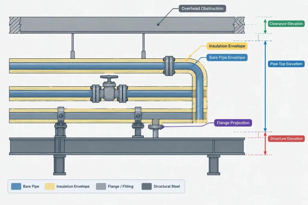
Insulation does not change the pipe centerline, BOP, TOP, or invert when those terms are defined relative to the bare pipe. It does change the external space required by the installed line. Clearance reviews should account for the insulation envelope separately, including local covers and removable sections where applicable.
An internal lining reduces the available bore and can move the effective internal flow surface. If invert is a design control, the project should define whether it refers to the metal pipe interior, the finished lining surface, or another hydraulic reference.
Flanges, valves, strainers, branch connections, vents, drains, and supports often extend beyond the basic pipe cylinder. Elevation notation should therefore be paired with envelope checks rather than treated as a complete clearance analysis.
A Practical CAD Review Workflow
- Confirm the datum. Identify the project elevation datum and do not mix it with local model coordinates without a documented transformation.
- Identify the controlled reference. Determine whether the design is controlled by centerline, BOP, TOP, invert, or an installed outer envelope.
- Verify the pipe data. Use the correct outside diameter and wall thickness for the specified size and wall system.
- Check transitions. Review reducers, wall changes, branches, and equipment connections for unintended shifts.
- Review the full envelope. Include insulation, flanges, valve bodies, operators, supports, and small-bore attachments.
- Check sloped runs at defined stations. Ensure each called-out elevation has an unambiguous location.
- Compare deliverables. Reconcile plans, sections, isometrics, model properties, and support drawings.
- Label exceptions. If one area uses invert while the rest of the drawing uses centerline, state the exception clearly.
Drafting Practices That Reduce Ambiguity
Use a consistent abbreviation and include the reference directly in the callout. Do not rely on elevation symbol placement alone to communicate whether the value applies to the centerline or a pipe surface. Where multiple lines overlap in plan, use sections or detail views to connect each elevation to the correct pipe.
At changes in size, slope, or reference method, show enough information for the geometry to be reconstructed without guessing. Avoid giving centerline, BOP, TOP, and invert values simultaneously unless each value serves a real coordination purpose and all are derived from the same verified pipe data.
Clear pipe elevation notation is ultimately a data-control practice. When the datum, reference surface, size, wall, slope, and callout location agree, elevations become reliable inputs for routing, fabrication, support coordination, and field installation rather than isolated numbers on a drawing.
Using Elevation Notation as Controlled Design Data
An elevation callout should be treated as controlled design data rather than a descriptive note. The model property, drawing annotation, and physical feature must all refer to the same location. If a tag reports centerline while a reviewer assumes BOP, both parties may believe the drawing is correct while evaluating different geometry.
Separate the Routing Reference from the Clearance Envelope
The reference used to route a line does not have to represent its limiting clearance. A pipe may be modeled by centerline while the coordination check is governed by insulation, a flange, a valve body, an operator, a support, or another projection. Drawings and model reviews should identify which value controls routing and which geometry controls clearance.
Keep Callouts Traceable Through Revisions
Changes to pipe size, wall selection, reducer orientation, slope, lining, or insulation can affect derived elevations even when the original control point remains fixed. Derived tags should be reviewed after geometry changes rather than assumed to update correctly in every view or exported deliverable.
Questions for Drawing and Model Handoffs
- Is the project datum identified and consistent across disciplines?
- Does every elevation label name its reference, such as CL, BOP, TOP, or invert?
- For sloped piping, is the station or attachment point of each elevation clear?
- Are bare-pipe references distinguished from insulation and installed envelopes?
- Do reducers and wall changes preserve the intended surface or axis?
- Have component projections and support geometry been checked separately from the pipe cylinder?
- Do plans, sections, isometrics, and model properties report compatible information?
Final interpretation should follow the project legend, drafting procedure, piping specification, and verified model geometry. When conventions differ between disciplines, an explicit note is safer than relying on abbreviation placement or customary practice.
Frequently Asked Questions
Is BOP the same as invert elevation?
No. BOP normally refers to the lowest outside surface of the bare pipe, while invert refers to the lowest internal flow surface. Pipe wall thickness separates the two references.
Does BOP include pipe insulation?
Not unless the drawing defines it that way. BOP generally describes the bare pipe. The bottom of insulation or another installed outer envelope should be identified separately when it controls clearance.
Why is centerline commonly used for pressure-piping layouts?
Centerline provides a consistent axis for routing straight pipe, fittings, branches, valves, and equipment connections. It does not, however, describe the complete outside envelope of the line.
Can centerline elevation be converted to BOP or TOP?
Yes, when the actual outside diameter is known and the pipe is circular. The conversion must use verified dimensional data rather than treating nominal pipe size as outside diameter.
Which elevation should be shown for sloped drainage pipe?
Invert elevation is commonly important because it defines the internal flow path. Each elevation must also be tied to a clear station, endpoint, connection, or other defined location along the slope.
What happens to elevations at a reducer?
The result depends on reducer type, orientation, and the reference being held. A transition may preserve the centerline or a selected outside surface, but it generally cannot preserve every pipe reference simultaneously.
Does a constant BOP guarantee clearance for the entire piping assembly?
No. Flanges, valves, branches, drains, supports, insulation, and other items may extend below the pipe surface. The complete installed envelope requires a separate coordination check.