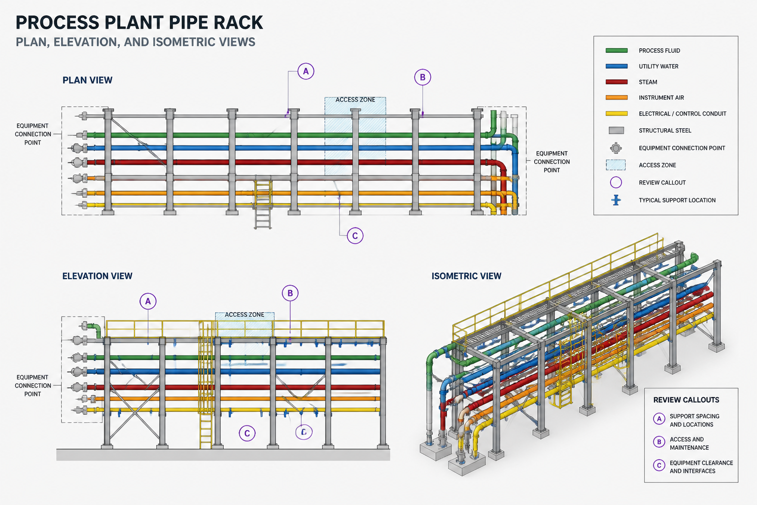
Developing a pipe rack layout in CAD is a coordination task before it is a detailing task. The most reliable workflow starts with project inputs, establishes a shared reference system, organizes routes by behavior, and then develops the plan, elevation, section, and model views needed for review.
This guide explains how to turn line data and interface information into a clear, reviewable arrangement while keeping assumptions visible and avoiding premature fabrication-level detail.
A well-organized pipe rack layout does more than place lines on a structure. It coordinates process piping, utilities, access, supports, maintenance needs, and the information required for construction. In CAD, the most effective workflow is to establish the arrangement logic first and add detail only after the major interfaces are understood.
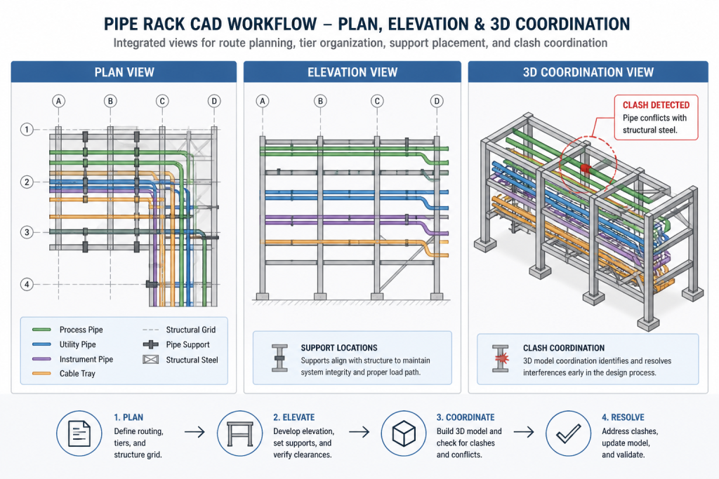
This guide focuses on the drafting and coordination process. It does not replace project design criteria, structural engineering, piping flexibility analysis, fire protection requirements, or owner standards. Use the project piping material specification, line list, equipment data, and approved design documents as the controlling references.
What a pipe rack layout must communicate
A pipe rack drawing should allow a reviewer to understand how piping travels through the structure and how that routing relates to nearby equipment and access areas. Depending on the project stage, the layout may be shown in plan, elevation, section, or a coordinated 3D model.
At minimum, the drawing should make the following relationships clear:
- Which lines occupy each routing zone or tier
- Where lines change direction, rise, drop, or leave the rack
- How piping connects to equipment, sleepers, buildings, or other structures
- Where support locations are intended or still require engineering confirmation
- Which areas must remain accessible for operation, inspection, removal, or maintenance
- How the rack aligns with grid lines, columns, beams, platforms, and foundations
The drawing should also distinguish verified information from working assumptions. A preliminary route may be suitable for arrangement review but not for fabrication or field installation.
Start with design inputs instead of geometry
Before drawing the rack, collect the information that controls the arrangement. The line list identifies line numbers, sizes, services, insulation information, and other attributes. The piping material specification identifies permitted components and connection details. Equipment drawings establish nozzle locations and orientation. Structural drawings define the available framing and load-transfer concept.
Review the project’s line routing criteria, equipment layout, plot plan, and existing CAD layer convention before creating new geometry. If the project includes a 3D model, use it as a coordination source rather than relying on isolated 2D blocks or copied details.
A useful input review separates information into three groups:
- Fixed points: equipment nozzles, battery limits, building penetrations, road crossings, and known tie-in points.
- Controlled zones: access ways, maintenance areas, electrical spaces, instrument locations, and areas reserved for future connections.
- Flexible routing: straight runs and branch arrangements that can move without changing the major interfaces.
Establish the rack reference system
Set up the drawing with a consistent project coordinate system. Show structural grid lines, column lines, rack centerlines, orientation markers, and key elevations. These references make later review much easier than dimensioning every pipe from unrelated objects.
Use a clear naming method for rack segments, tiers, and sections. A line should be traceable from its source to its destination without forcing the reviewer to infer the route from scattered views. Match line numbers and equipment tags to the approved project data, and avoid creating unofficial abbreviations that could be confused with piping specifications.
Group lines by routing behavior
Pipe rack organization is usually more effective when lines are grouped by service and routing behavior rather than arranged solely by size. Large or heavy lines may influence structural framing and support concepts. Lines connected to equipment may need a direct route or controlled flexibility. Utility lines may be grouped for efficient distribution and easier future modification.
Typical grouping questions include:
- Which lines need to remain together for a common destination or utility header?
- Which lines require special attention because of temperature, movement, insulation, or cleanliness?
- Which lines frequently branch to process units or equipment?
- Which routes should remain available for future tie-ins?
- Which lines must avoid access, electrical, instrumentation, or drainage zones?
Do not assume that the largest line belongs at the lowest or highest tier in every project. The final arrangement depends on the project’s process, structural, access, flexibility, and constructability requirements.
Develop the layout in plan and elevation
Begin with a simplified plan showing rack boundaries, columns, primary corridors, equipment interfaces, and major line centerlines. At this stage, use lightweight graphics and avoid adding every flange, bolt, weld, or support shoe. The objective is to confirm routing logic.
Next, develop elevations or sections at locations where vertical relationships matter. These views help reveal conflicts that are easy to miss in plan, including overlapping branches, inadequate access zones, congested crossings, and unclear changes between rack tiers.
| View | Best used for | Common review question |
|---|---|---|
| Plan | Horizontal routing, columns, branches, and interfaces | Does each line have a coherent path through the rack? |
| Elevation | Tier organization, vertical offsets, and equipment connections | Are the vertical relationships and access zones understandable? |
| Section | Congested areas, support concepts, and clearances | Can the reviewer see relationships hidden in plan or elevation? |
| 3D model | Overall coordination and spatial review | Do piping, steel, equipment, and access areas occupy the same space? |
Coordinate supports without overstating the design
A pipe rack layout should show the intended support strategy, but a preliminary arrangement is not the same as a completed support design. Use support markers, reference notes, or support IDs that clearly indicate the current design status.
Coordinate the piping concept with the structural model. A pipe support placed directly over a beam may still require review for load transfer, local effects, movement, or installation access. Likewise, a line that appears supported in plan may need a different arrangement after flexibility analysis or detailed structural coordination.
Where the layout depends on a support calculation, guide, anchor, spring, or special restraint, identify the requirement without inventing a final detail. Link the drawing to the project support schedule or engineering deliverable when available.
Check access, maintenance, and constructability
Routing that fits geometrically can still be difficult to build or operate. Review the rack as a working environment, not only as a collection of centerlines.
- Can valves, instruments, drains, vents, and specialty components be reached as intended?
- Can removable items be extracted without conflicting with steel or adjacent piping?
- Are field welds, flanged joints, and inspection areas located where installation crews can work?
- Do branch connections create congestion at columns, beams, platforms, or ladders?
- Are expansion, movement, and thermal routing assumptions clearly identified for later analysis?
- Are future connections shown as reserved space rather than implied by undocumented empty areas?
Use the model and drawings to flag issues for review. Do not hide a conflict by moving a line without recording the design decision or checking the affected interface.
Use CAD layers and annotations consistently
A practical CAD setup separates piping, structural steel, equipment, dimensions, centerlines, hidden items, notes, and review markups. The exact layer names should follow the project standard, but the principle is consistent: a reviewer should be able to isolate disciplines and understand drawing status quickly.
Keep line numbers and equipment tags readable at the chosen drawing scale. Use consistent symbols for direction changes, continuation references, drains, vents, and support identifiers. If a line is shown schematically rather than at fabrication level, state that in the drawing notes or title block.
Final pipe rack layout review
Before issuing the drawing, perform a structured review rather than relying on visual confidence. Confirm that each routed line can be traced between its known endpoints, every major branch appears in the appropriate views, and all interfaces agree with the latest equipment and structural information.
- Verify line numbers, service descriptions, and connection points against the current line list.
- Check that plan, elevation, section, and model views use consistent coordinates and elevations.
- Review structural grids, column locations, platforms, access routes, and reserved areas.
- Confirm that support markers and special restraint notes have an identifiable design status.
- Record unresolved clashes, assumptions, and items requiring piping flexibility or structural review.
- Remove obsolete geometry and superseded tags before issuing the drawing.
A strong pipe rack layout is a coordination document: it explains the route, exposes design decisions, and gives other disciplines enough information to review their interfaces. When the drawing separates confirmed data from assumptions and uses consistent references across plan, elevation, section, and model views, it becomes far more useful than a crowded arrangement that merely appears complete.
How to use this workflow effectively
The workflow is most useful when each drafting decision can be traced to a project input or a coordination requirement. Before moving a route, identify the affected line, equipment connection, structural reference, access area, or support assumption. This creates a design record that is easier for piping, structural, electrical, instrumentation, and construction reviewers to understand.
Separate arrangement maturity from drawing appearance
A drawing can look detailed while still containing unresolved routing, support, flexibility, or access decisions. Use drawing notes, review status, support identifiers, and clash records to show what has been confirmed and what remains subject to engineering review. This distinction is especially important when a CAD arrangement is shared before fabrication or field installation.
Use views as complementary checks
Plan views are effective for tracing horizontal routes and interfaces. Elevations and sections expose vertical relationships, congestion, and support concepts that may be hidden in plan. A coordinated model can help reviewers understand the overall spatial arrangement, but it should remain consistent with the approved line data, equipment information, structural references, and project CAD conventions.
Build useful internal references
For a broader drafting reference, connect this workflow to the project’s line routing criteria and CAD layer convention. Related resources on pipe dimensions and schedules, piping fittings, and pipe flanges can support component identification without replacing the project specification or approved design documents.
Pipe rack layout in CAD FAQ
What should be shown first in a pipe rack layout?
Start with fixed interfaces, rack boundaries, structural references, major routing corridors, equipment connections, and primary line centerlines. Add detailed components after the overall routing logic has been reviewed.
Should pipe rack lines be grouped only by size?
No. Grouping should also consider service, destination, branching behavior, insulation, movement, support needs, access, and future routing requirements. The final arrangement should follow project engineering and coordination requirements.
Which CAD views are needed for pipe rack coordination?
Plan, elevation, and section views serve different review purposes. A coordinated three-dimensional model can supplement these views by showing how piping, steel, equipment, supports, and access areas share the same space.
Does a pipe rack layout complete the support design?
No. The layout can communicate an intended support strategy and identify locations requiring review, but final support details may depend on structural checks, piping flexibility analysis, movement requirements, and project deliverables.
How can a drawing show unresolved design decisions?
Use clear status notes, support identifiers, review markups, assumption records, and clash or interface logs. Do not make unresolved items appear final through undocumented geometry changes or overly detailed symbols.
What is the final review objective?
The objective is to confirm that lines can be traced between their known endpoints, interfaces agree across the relevant views, access and maintenance needs are visible, and unresolved engineering or coordination items are recorded for disposition.