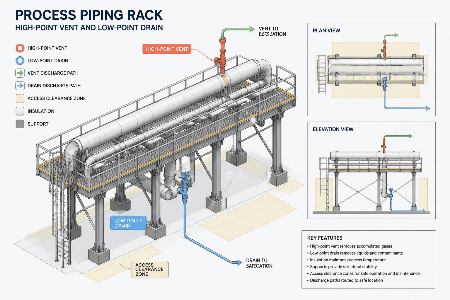
Detailing piping vents and drains in CAD requires more than placing a small branch and valve symbol on a drawing. Each connection must communicate its purpose, physical location, operating arrangement, discharge path, and relationship to the surrounding piping and equipment.
This guide explains a practical review method for carrying vent and drain intent from process documents into coordinated plan, elevation, and isometric views. Use it alongside the project piping material specification, P&ID, line list, equipment information, and applicable design procedures.
Piping vents and drains are small connections with a large effect on operability. They help remove trapped gas, empty piping, prepare equipment for maintenance, and make hydrostatic testing or flushing practical. In a CAD model or piping drawing, however, these items are easy to omit, place on the wrong side of a line, or show without enough information for fabrication and operation.
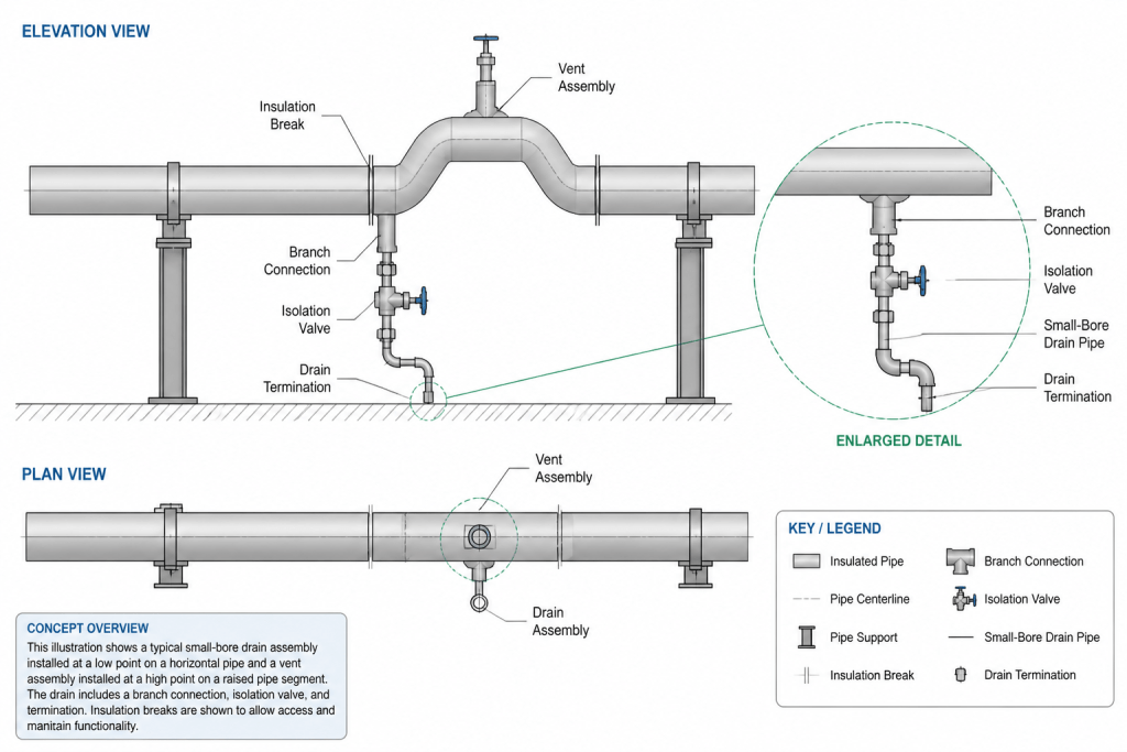
A reliable detailing process starts with the process documents and piping material specification, then carries that intent into the plan, elevation, isometric, and equipment interface details. The goal is not to add vents and drains by visual habit. It is to show the required connection, valve arrangement, discharge direction, access, and identification clearly enough that the design can be reviewed and built.
What piping vents and drains do
A vent provides a path for gas or vapor to leave a piping system. It is commonly associated with high points, equipment tops, trapped sections, or locations where air removal is needed during filling. A drain provides a path for liquid to leave a system. It is commonly associated with low points, equipment bottoms, dead legs, or sections that must be emptied for maintenance or testing.
These are functional descriptions, not automatic placement rules. Actual locations depend on the service, line routing, required slope, equipment arrangement, operating procedure, environmental controls, and project specifications. A high point may not need a vent if the system arrangement provides another suitable path, and a low point may require a drain connection with a particular valve or discharge arrangement.
Before drafting, confirm the intent using the piping material specification, P&ID, line list, equipment drawings, and project notes. Do not infer a complete vent or drain design from the geometry alone.
Identify the vent or drain before opening the CAD detail
Start by building a short review list for each relevant line or equipment connection. Record the information that affects the drawing:
- The line number and service associated with the connection.
- Whether the item is a vent, drain, sample point, flushing connection, or another small-bore branch.
- The connection size, end type, rating, material, and valve requirements from the project data.
- The destination of the discharge, such as a closed drain system, safe collection point, vent header, or designated local location.
- Whether the connection is normally open, normally closed, locked, capped, plugged, or operated only during maintenance.
- Any access, insulation, heat tracing, hazardous-area, or environmental constraints.
This information prevents a common CAD error: showing a generic valve symbol while leaving the actual connection and destination undefined. A vent or drain is not complete merely because a branch appears on the line.
Use the model geometry to find likely locations
Once the process intent is known, inspect the three-dimensional route and its drawing views. Look for points where the physical arrangement can trap gas or liquid:
- High points created by changes in elevation or locally raised piping.
- Low points created by pockets, offsets, or changes in slope.
- Closed sections between valves, blinds, check valves, or equipment nozzles.
- Equipment connections that cannot be emptied or vented through the normal process route.
- Temporary or permanent test boundaries identified in the construction or commissioning plan.
Review the route in plan and elevation, not only in the isometric. A line that looks continuous in an isometric may contain a hidden high or low point when its elevation changes are checked. Coordinate dimensions and elevation callouts should make the relevant geometry verifiable without requiring the reviewer to guess from a crowded view.
For sloped lines, check that the vent or drain is associated with the actual high or low point rather than simply the nearest elbow. The connection may need to be placed on a straight segment, at an elbow, or on a fitting depending on the piping specification and fabrication practice. The drawing should reflect the approved arrangement, not an assumed rule.
Show the complete connection arrangement
A small-bore connection usually needs more information than a single branch line. The drawing should communicate how the connection is assembled and used. Depending on the design, that may include:
- The branch connection type and orientation.
- The valve symbol and valve identification.
- A blind, cap, plug, threaded end, flanged end, or quick connection where specified.
- A short spool, nipple, reducer, or other fitting needed to connect the valve to the main pipe.
- A routed discharge line leading to its intended destination.
- A support or restraint where the small-bore assembly could impose load on the main pipe or valve.
Use the project symbology consistently. If a vent or drain is intended for occasional operation, the drawing should not make it appear to be an open-ended discharge. Conversely, do not hide a required open drain behind a generic termination symbol. The end condition matters for both operation and safety review.
Detail vents and drains across different drawing views
Plan and elevation views
Use plan and elevation views to establish physical position, orientation, access, and clearance. A drain valve below a pipe may need a separate elevation detail if the main view makes the valve appear to clash with steel, insulation, flooring, or another line. A high-point vent may need an elevation callout to show how it rises above the pipe and where the discharge proceeds.
Piping isometrics
On an isometric, show the branch, valve, fittings, and continuation far enough to communicate the assembly. Include the item in the bill of materials or component list when the project workflow requires it. The isometric should also make the connection location traceable to the line route and related P&ID information.
Small-bore items are often lost when linework is dense. Use a detail bubble, enlarged area, or offset annotation when the standard isometric scale cannot show the arrangement clearly. Avoid moving the connection graphically without a clear reference to its true location.
Equipment and piping interface details
Where a vent or drain connects directly to a vessel, pump, filter, heat exchanger, or other equipment item, coordinate the detail with the equipment nozzle orientation and maintenance envelope. A connection that is technically present but blocked by a removable cover, lifting path, platform, or insulation is not adequately detailed.
Check access, discharge, and maintenance intent
CAD review should test more than connectivity. Ask practical questions about how the item will be used:
| Review area | Questions to ask |
|---|---|
| Access | Can an operator or maintenance worker reach the valve, cap, or plug without an unreasonable obstruction? |
| Orientation | Does the handle, actuator, or removable end have usable clearance and a sensible operating direction? |
| Discharge | Is the outlet directed to the intended system or collection point rather than toward equipment, walkways, or inaccessible spaces? |
| Drainability | Does the shown geometry actually allow the intended section to empty, or does another pocket remain? |
| Ventability | Can trapped gas reach the shown vent, or is a higher point still present in the route? |
| Maintenance | Can the connection be isolated, removed, and reassembled using the specified components? |
These are design-review prompts, not substitutes for the project operating procedure, safety review, or applicable engineering requirements. The responsible design team must confirm the final arrangement.
Common CAD mistakes with vents and drains
- Adding a symbol without a destination: A valve shown at the pipe is not enough if the discharge route is part of the design intent.
- Ignoring the elevation: A drain placed near a low area may not drain the complete section if the true low point is elsewhere.
- Using the wrong line specification: Small-bore branches still require the correct material, rating, end connection, and valve selection.
- Hiding the item under insulation: The connection and operating access should remain understandable in the insulation and support details.
- Leaving out the item list entry: A component omitted from the bill of materials can create fabrication and procurement discrepancies.
- Overcrowding the isometric: When symbols and notes overlap, use a controlled detail rather than reducing the drawing to unreadable scale.
A practical final-check workflow
Before issuing the drawing, trace each vent and drain from the source document to the CAD model and drawing views. Confirm that the line number, location, component arrangement, specification data, and destination agree. Then review the item in plan, elevation, and isometric views for consistency.
Finally, check the connection against nearby supports, platforms, insulation, structural steel, access ways, and removable equipment. Compare the drawing with the project’s pipe support details and piping isometric checklist so the small-bore assembly is not treated as an isolated annotation. A clear vent or drain detail connects process intent, physical geometry, fabrication information, and field usability in one verifiable package.
How to make vent and drain details easier to review
A good CAD detail allows another person to answer the important questions without reconstructing the design from scattered notes. The connection should be identifiable in the model, traceable to the relevant line or equipment item, and represented consistently wherever it appears in the deliverable.
Keep model data and drawing graphics consistent
Where the CAD system supports component properties, use the same identification and specification information for the model object, isometric annotation, and component list. A graphical symbol that does not match the modeled valve, fitting, or end condition can create errors during checking and material takeoff.
Use controlled detail views for crowded areas
When a small-bore assembly is difficult to read at the normal drawing scale, create a clearly referenced detail rather than enlarging or shifting geometry without explanation. The detail should identify the true connection location and preserve the relationship to the main line, nearby supports, insulation, and access route.
Review the connection as an operating feature
During checking, follow the expected use of the vent or drain. Consider how the line is isolated, where fluid or gas travels, how the valve or termination is reached, and what must be removed or disconnected during maintenance. This operational walk-through often reveals omissions that a purely geometric clash check will not find.
Coordinate related reference documents
Use the project piping isometric checklist to confirm drawing consistency, and compare the arrangement with pipe support details where the small-bore branch may require restraint or protection. Equipment interface drawings, insulation details, access studies, and commissioning documents may also affect the final representation.
The final objective is a verifiable detail: a reviewer should be able to identify what the connection does, where it is located, how it is assembled, where it discharges, and how it can be operated or maintained without relying on assumptions.
Frequently asked questions
Where should a piping vent be shown in CAD?
Show the vent at the approved location identified from the process documents and the actual three-dimensional piping geometry. Review high points, equipment interfaces, trapped sections, and the intended gas-removal path rather than placing the symbol by visual habit.
Where should a piping drain be shown in CAD?
Show the drain at the approved low point or other location required by the design intent. Check the complete route in plan and elevation so the connection can empty the intended section and does not leave another pocket unaddressed.
What information should a vent or drain detail include?
The detail may need the branch connection, valve, end condition, fittings, discharge continuation, identification, specification information, and any required support or restraint. The exact arrangement must come from the project documents and piping specification.
Why are plan and elevation views important for vents and drains?
They establish elevation, orientation, access, clearance, and the relationship to nearby structures or equipment. An isometric alone may not make a hidden high point, low point, or obstruction clear.
How can CAD reviewers find omitted vents and drains?
Trace each connection from the P&ID, line list, equipment information, and model into every required drawing view. Then check the destination, component list, access, discharge direction, insulation, supports, and maintenance envelope.