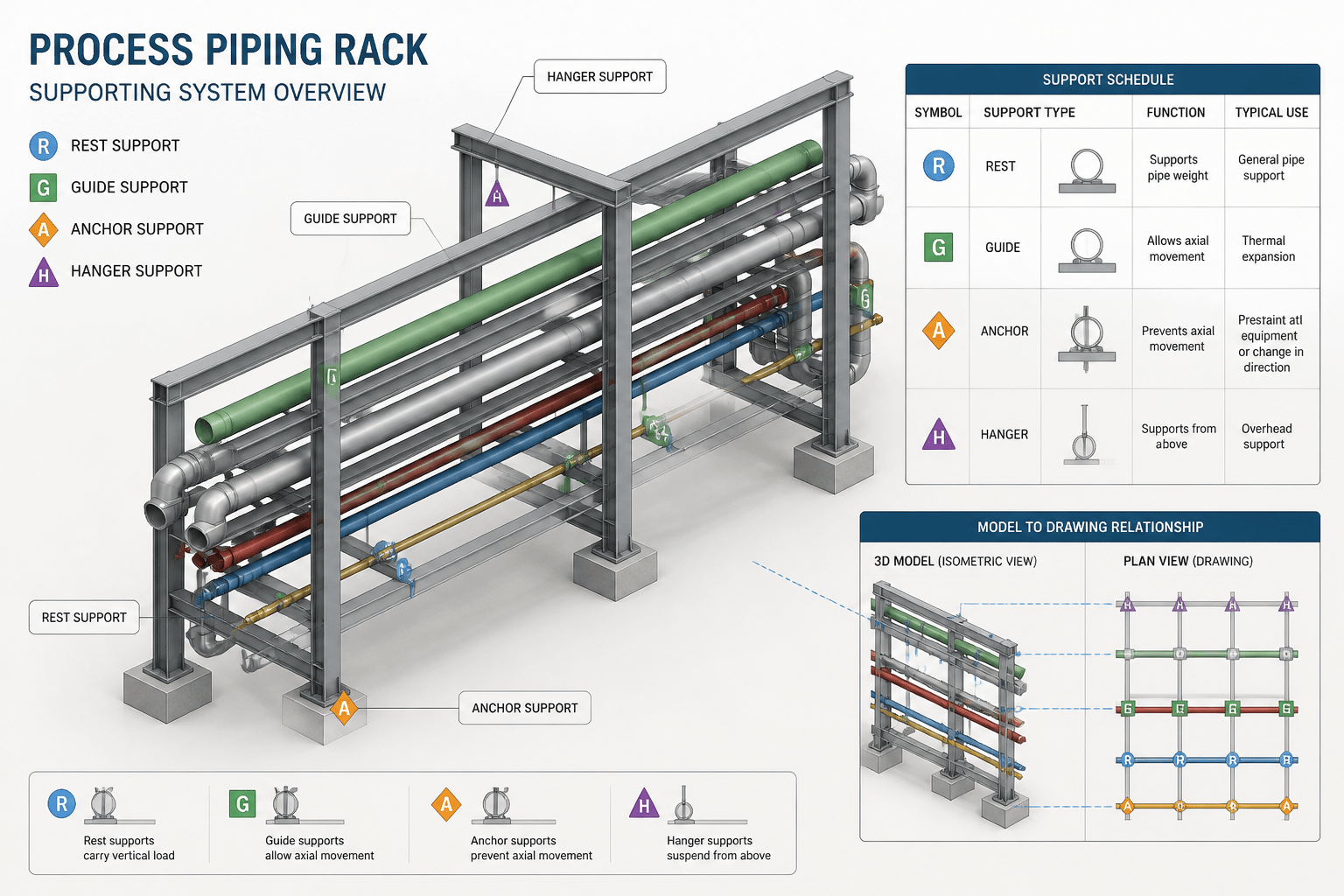
A piping support schedule in CAD turns support information into a traceable project record. It links modeled support objects with pipe lines, drawings, structural interfaces, support details, and installation requirements.
For designers and drafters, the schedule is most useful when it is treated as controlled coordination data rather than a simple list. This guide explains what the schedule should communicate, how to assemble it from project documents, and how to check it against the current model and drawing set.
Before assigning support information, establish which documents control the piping arrangement and support intent. Related resources on piping material specifications, insulated piping CAD detailing, and pipe spool drawing workflows can help define the interfaces that a schedule must preserve.
A piping support schedule connects the physical arrangement of a pipe system to the support information needed for design, modeling, detailing, procurement, and construction. It may appear as a compact table, a model report, or a drawing index, but its purpose is the same: identify each support, describe its relationship to the pipe, and provide enough information for other disciplines to verify the arrangement.

A support schedule is not a substitute for a support design calculation or a project specification. It is a coordination tool. When it is prepared carefully, it helps designers find missing supports, compare model data with drawings, and communicate support locations without overcrowding an isometric.
What a piping support schedule usually contains
The exact columns vary by company and project, but a useful schedule normally combines identification, location, type, and coordination information. The most important rule is consistency: the same support identifier and description should be used in the CAD model, piping isometric, general arrangement drawing, and any related support detail.
| Schedule field | Purpose | Typical checking question |
|---|---|---|
| Support tag | Provides a unique reference for the support. | Does the tag appear only once in the relevant area or line group? |
| Support type | Describes the functional arrangement, such as a rest, guide, anchor, hanger, or specialty support. | Does the type match the symbol and physical arrangement shown in the drawing? |
| Pipe or line reference | Connects the support to the supported piping. | Can the support be traced back to the correct line number? |
| Location | Identifies a coordinate, station, weld reference, fitting reference, or drawing location. | Can a fabricator or installer locate it without guessing? |
| Elevation or orientation | Communicates vertical position, support direction, or orientation where needed. | Is the reference system clearly defined? |
| Detail reference | Points to a standard, project, or specially engineered support detail. | Does the referenced detail exist and apply to this support? |
| Remarks | Records coordination notes, field conditions, insulation interfaces, or installation restrictions. | Are remarks specific enough to affect the work? |
Some schedules also include material information, support steel references, load data, coating requirements, or status fields. These should be included only when the project workflow defines who owns and verifies the information. Adding columns that no one maintains can make a schedule look complete while reducing its reliability.
Start with the design basis, not the table format
Before creating a schedule, identify the documents that define the piping arrangement and support intent. Depending on the project, this may include the piping material specification, line list, piping and instrumentation diagram, stress analysis deliverables, equipment drawings, structural drawings, support detail library, and project CAD standards.
These documents answer different questions. A line list may identify the line and service. A piping model shows the route and components. A stress deliverable may define support functions or special constraints. A structural drawing shows available steel or concrete interfaces. A support detail library explains how a support is represented and fabricated. The schedule should not silently replace any of them.
For background, review the project’s piping material specification before assigning support materials or connection details. When a support is attached to insulated piping, coordinate it with the insulated piping detailing workflow rather than treating insulation as an afterthought.
A practical workflow for building the schedule
1. Establish the support numbering method
Choose a tag structure that is unique, readable, and compatible with the project document system. A tag may include an area, unit, discipline prefix, or sequential number, but the format should be defined before large-scale modeling begins.
Do not reuse a tag merely because two supports look similar. Each physical support should be traceable. If a support is revised, retain the identity rules required by the project instead of creating an informal replacement that cannot be tracked.
2. Extract candidate supports from the model and drawings
Use the 3D model, isometrics, support sketches, and layout drawings together. A model report may find tagged supports, but it may not identify an unmodeled steel interface or a support shown only on a detail drawing. Conversely, a drawing mark-up may show an intended support that has not yet been added to the model.
Create a working list and record the source of each entry. This makes later reconciliation easier and exposes gaps between design intent and documented geometry.
3. Describe the support by function and arrangement
A short support description should tell the reader what the support does and what it is connected to. Avoid descriptions that rely only on a catalog-style code unless that code is universally understood within the project.
Distinguish between functions such as vertical support, lateral guidance, axial restraint, line stop, anchor, spring support, and variable or special support. The visual appearance may be similar in a simplified CAD view, but the functional distinction can affect routing, movement, stress coordination, and installation.
4. Define the location reference
A support location should be reproducible. Depending on the drawing system, useful references include a pipe centerline coordinate, an isometric location, a distance from a weld or fitting, a structural grid, or a support point identified in the model.
Avoid vague descriptions such as “near elbow” or “at rack.” Use a reference that survives reasonable drawing revisions. If the support is associated with a pipe shoe, clamp, trunnion, or attachment, identify the supported component and its relationship to the pipe centerline.
5. Link the schedule to the right detail
Support details should distinguish standard arrangements from project-specific designs. A schedule entry can reference a detail number, but the detail must be available to the people who need it and must match the support shown in the model.
Pay particular attention to attachments near elbows, branches, valves, flanges, and equipment nozzles. These locations often require coordination with access, maintenance, flexibility, insulation, and lifting requirements. A generic support symbol does not resolve those interfaces by itself.
CAD checks that prevent common schedule errors
- Duplicate tags: Search the model and drawing set for repeated identifiers.
- Orphaned entries: Find schedule rows with no matching model object, drawing callout, or detail.
- Unlisted supports: Compare visible supports in plans, sections, and isometrics against the schedule.
- Incorrect line association: Verify that the support is attached to the intended line, not a nearby parallel pipe.
- Location mismatch: Compare the schedule reference with coordinates, gridlines, welds, fittings, and structural members.
- Orientation mismatch: Check guides, stops, anchors, and directional supports against the actual pipe movement or routing intent.
- Detail mismatch: Confirm that the referenced support detail shows the same attachment and installation arrangement.
- Revision mismatch: Ensure the schedule, model, isometric, and support drawings were generated or checked from compatible revisions.
Layering and display controls can make these checks faster. Create a view that isolates supports, support tags, centerlines, structural references, and equipment interfaces. A separate review view often reveals an incorrectly oriented support more clearly than a crowded fabrication sheet.
How to handle support schedules on isometrics
Do not force every support attribute onto the isometric. The isometric should identify the support clearly and provide a usable location reference; the schedule or detail drawing can carry the longer description. This division keeps the drawing legible while preserving traceability.
Use a consistent callout strategy. Place the tag near the support location, avoid covering dimensions or weld symbols, and use a continuation or reference note when the support is outside the primary view. If the support is shown symbolically, make sure the symbol library distinguishes support functions that matter to the reviewer.
Support callouts should also be coordinated with spool boundaries. A support attached to a field weld, shop weld, or prefabricated fitting can affect fabrication planning. This is one reason to review support information while preparing a pipe spool drawing, rather than adding it after spools have been issued.
When the schedule is ready for issue
A piping support schedule is ready for a formal review when every row has an owner, a traceable location, a matching CAD or drawing reference, and an applicable detail or disposition. Reviewers should be able to determine what the support is, where it is, what it connects to, and which document controls its design.
Keep the schedule synchronized with the model and drawing revisions. If a pipe route moves, a fitting changes, or a support function is revised, check whether the tag, location, detail reference, structural interface, and installation notes are still valid. A schedule is valuable because it exposes these relationships; it becomes risky when it is treated as a static export.
Final checklist
- Every physical support has a unique and traceable tag.
- Every schedule row points to the correct pipe or line.
- Support functions are described clearly rather than inferred from an unfamiliar code.
- Locations can be reproduced from the model or drawing set.
- Support details match the modeled arrangement and project requirements.
- Insulation, access, equipment, structure, and fabrication interfaces have been reviewed.
- Isometric callouts remain readable and do not obscure primary dimensions.
- The schedule has been checked against the current model and drawing revision.
Used this way, a piping support schedule is more than a list of tags. It is a controlled interface between piping design, stress coordination, structural design, CAD detailing, fabrication, and field installation.
How to read a piping support schedule
Read each row as a link between a physical support and the documents that explain or control it. Start with the support tag, then confirm the supported line, functional type, location reference, orientation, detail reference, and remarks. A row is dependable only when those references describe the same physical arrangement.
When reviewing a schedule, separate three questions:
- Identity: Which support is being referenced, and can it be found only once?
- Location: Where is the support in relation to the pipe, fittings, structure, equipment, or drawing reference?
- Disposition: Which detail, design document, or project instruction governs its arrangement?
Why schedule quality depends on data ownership
Not every useful-looking column belongs in every schedule. Material, load, coating, structural, and status information should be included only when the project defines who maintains and verifies it. A short schedule with dependable ownership is more useful than a detailed schedule containing unchecked fields.
Use the schedule as a coordination layer, not as a replacement for stress analysis, support calculations, structural design, project specifications, or fabrication details. This distinction helps reviewers understand what the schedule confirms and what must be verified in another deliverable.
Practical review strategy
A reliable review compares the schedule with the model, isometrics, support details, structural references, and relevant equipment interfaces. First check completeness, then check consistency. Completeness asks whether supports shown in the design are represented. Consistency asks whether the tag, line association, location, orientation, and detail all agree across documents.
For efficient CAD review, create a dedicated support view that isolates support objects, tags, pipe centerlines, structural references, and equipment interfaces. Record discrepancies by support tag and document revision so that corrections can be traced instead of being resolved informally.
Common interpretation mistakes
- Assuming a support symbol communicates its complete function without checking the schedule or detail.
- Using a nearby gridline or equipment reference that does not uniquely locate the support.
- Copying a support row after a pipe route changes without rechecking its line and location references.
- Adding project-specific material or load information without confirming the responsible discipline.
- Treating a schedule export as current without comparing its source model and drawing revisions.
Frequently asked questions
What is the purpose of a piping support schedule?
It connects physical pipe supports with the identification, location, function, detail, and coordination information needed by design, CAD, fabrication, construction, and review teams.
Is a piping support schedule a support design calculation?
No. It is a coordination tool and does not replace support calculations, stress deliverables, structural design, project specifications, or engineered support details.
What should a support schedule row identify?
A useful row normally identifies the support tag, support type, supported pipe or line, location, orientation or elevation reference where needed, applicable detail, and relevant remarks.
How can CAD users find missing supports?
Compare the schedule with support objects in the model, support callouts on isometrics, plans, sections, and related detail drawings. A dedicated support review view can make omissions and mismatches easier to find.
Why are support tags important?
A unique tag allows the same physical support to be traced across the CAD model, isometric, general arrangement drawing, support detail, schedule, and revision record.
When should a support schedule be updated?
Update or recheck it whenever the pipe route, fitting, support function, structural interface, installation arrangement, or governing drawing revision changes.