
Clear CAD documentation depends on separating the pipe’s physical geometry from the information used to select and verify it. Wall thickness, nominal size, schedule, and corrosion allowance are related, but each serves a different purpose in a piping model or drawing.
This reference explains how to show the pipe appropriately for the deliverable, where to store thickness-related attributes, and how to review the resulting drawing without treating a graphic representation as proof of engineering suitability.
Pipe wall thickness is easy to misunderstand in a piping drawing because several related terms appear together: nominal pipe size, outside diameter, inside diameter, schedule, minimum thickness, and corrosion allowance. These terms do not describe the same thing, and treating them as interchangeable can create errors in CAD models, sections, bills of materials, and fabrication documents.
This guide explains how to represent pipe wall thickness in CAD without replacing the project’s governing material specification or authoritative dimension tables. The goal is to make the drawing communicate the selected pipe consistently and to help drafters identify where thickness information belongs in the design workflow.
What pipe wall thickness means
Pipe wall thickness is the radial distance between the outside surface and the inside surface of the pipe. In a simple circular section, the relationship between outside diameter, inside diameter, and nominal wall thickness can be expressed conceptually as:
Inside diameter = outside diameter − twice the wall thickness
That relationship is useful for understanding geometry, but it does not mean that every pipe has one perfectly uniform or constant usable dimension. Published dimensions may distinguish between nominal, calculated, minimum, specified, or measured values. Manufacturing tolerances, forming methods, lining, coating, and corrosion requirements can also affect how the pipe is represented or evaluated.
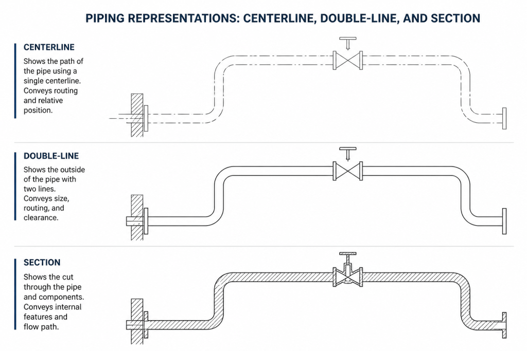
For most general arrangement and piping layout drawings, the pipe is shown as a centerline or a simplified double-line object rather than as a fully detailed solid. A detailed section or fabrication model may require more information. The drawing method should therefore match the purpose of the deliverable.
Nominal size and wall thickness are different identifiers
Nominal pipe size is a naming convention used to identify a pipe size range. It is not necessarily the same as the measured outside diameter or inside diameter. A pipe with a given nominal size can be available with different wall thickness selections, while its outside diameter convention may remain tied to that size family.
Schedule is one common way to identify a pipe wall category within compatible dimensional systems. It is not a universal thickness value that can be applied without checking the size, material specification, and governing standard. The actual wall associated with a schedule depends on the pipe size and the relevant reference data.
In a CAD environment, keep these properties separate:
- Nominal size: the size designation used in tags, specifications, and component selection.
- Outside diameter: the external geometric dimension used for clearances, supports, clamps, and physical coordination.
- Schedule or wall designation: the selected thickness category or pipe description required by the material specification.
- Inside diameter: a derived or published flow-path dimension that may be important for analysis and equipment interfaces.
- Corrosion allowance: an additional design consideration that may affect the required starting wall or engineering evaluation; it is not automatically a separate visible layer of pipe in every drawing.
How corrosion allowance relates to wall thickness
Corrosion allowance is an allowance made for anticipated material loss during the design life or service basis of a component. It should not be confused with pipe manufacturing tolerance, insulation thickness, lining thickness, or the wall thickness printed in a dimensional table.
A project may select a pipe wall or component based on a required condition after accounting for corrosion, erosion, wear, fabrication tolerance, pressure design, temperature, loads, and other engineering considerations. The selected nominal pipe description is then documented through the applicable material specification, line class, equipment data, or design basis.
For a drafter, the important distinction is this: corrosion allowance is usually a design input or specification attribute, while the CAD object represents the selected physical component. Do not create a thicker pipe graphic merely because a corrosion allowance exists unless the project’s modeling practice explicitly requires that representation.
Choosing the right CAD representation
Centerline representation
Centerline drawings are common for process schematics, early routing, and many piping isometrics. In this representation, wall thickness is not drawn to scale. The pipe’s nominal size and specification are communicated through line tags, component annotations, model properties, or a material list.
This method keeps the drawing legible, but it requires reliable metadata. A centerline alone cannot show whether two pipes with the same route have different wall selections. Use the line number, spec identifier, size designation, and component data to provide that distinction.
Double-line representation
Double-line plans and elevations show the pipe envelope and are useful when outside diameter affects coordination. They can help reviewers inspect gaps, structural penetrations, access areas, and connections to equipment. The visible gap between lines should be controlled by the drawing scale and drafting standard rather than exaggerated until it suggests an incorrect physical wall.
When the wall is too small to display clearly, use a symbolic or not-to-scale convention. Add a note or section detail when the actual wall relationship matters.
Section or solid representation
A section view or 3D solid can show the relationship between outside and inside surfaces. This is appropriate for selected details such as a pipe-to-fitting interface, a sleeve, a liner, a branch connection, or a penetration. It is not always necessary to model every pipe wall as a high-detail solid.
Before using a solid wall in a coordination model, confirm whether the model represents the nominal component, the external envelope, or a fabrication-ready geometry. Those are different purposes and can produce different modeling decisions.
Where to record thickness information
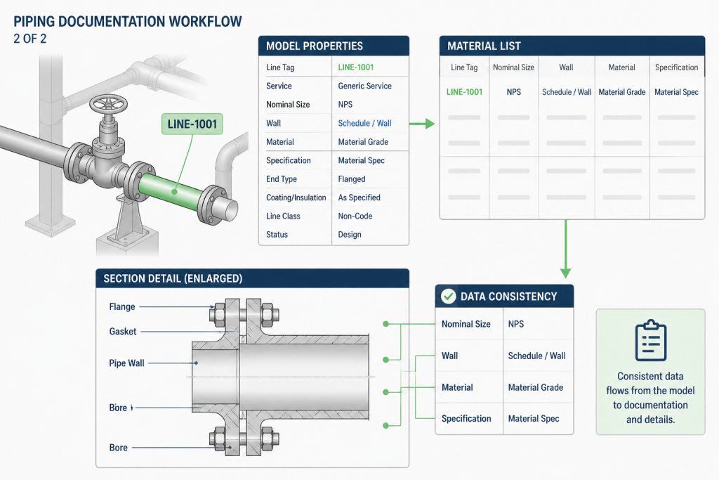
Wall information may appear in several places, and each location serves a different purpose:
| Drawing or model location | Useful information | Common checking question |
|---|---|---|
| Line tag or line list | Nominal size, service, specification, and line identity | Does the pipe trace to the correct material and service definition? |
| Material list or bill of materials | Pipe description, schedule or wall designation, material, and quantity | Does the listed component match the line specification? |
| Section detail | Outside surface, inside surface, lining, sleeve, or local interface | Is the geometry needed for coordination or fabrication? |
| Component properties | Size, wall category, material, end preparation, and catalog identity | Are model attributes consistent with the drawing annotation? |
| Design or specification documents | Corrosion basis, minimum requirements, and selection rules | Was the selected component approved for the intended design basis? |
CAD checks for wall and schedule consistency
A practical review should confirm both the graphical representation and the non-graphical data. Use the following sequence:
- Check the line identity. Confirm that the line number, service, size, and material specification are correct before reviewing the pipe geometry.
- Verify the pipe description. Compare the model or drawing property with the approved material list and the applicable dimension reference. Do not infer wall thickness from appearance.
- Check the external envelope. Review outside diameter, insulation, coating, support interfaces, penetrations, and nearby equipment. These coordination items often depend more directly on the external size than on the nominal wall.
- Review connections. Confirm that the pipe, fittings, flanges, valves, and branches use compatible size and specification data. A correct-looking centerline can still contain an incompatible component selection.
- Inspect sections where thickness matters. Use enlarged details for sleeves, linings, reducers, branch connections, threaded ends, weld preparations, and other interfaces that cannot be understood from a centerline.
- Check the bill of materials. Make sure the pipe description, schedule or wall designation, material, and quantity are generated from the same source data as the model.
- Separate design verification from drafting verification. The drafter can check whether the selected information is represented consistently, but engineering authority must verify the pressure, temperature, corrosion, erosion, and mechanical design basis.
Common drafting mistakes
- Scaling the wall from a small drawing: thin walls may be intentionally exaggerated or omitted for clarity.
- Using schedule as a direct universal thickness: the applicable size and reference system must be checked first.
- Adding corrosion allowance as a visible extra wall: this can misrepresent the modeled component unless required by the project method.
- Changing the outside diameter to show a thicker wall: this may create coordination errors when the pipe size family uses a fixed outside diameter convention.
- Leaving thickness data only in a note: critical component attributes should also be available in structured model or material data when possible.
- Assuming a fitting matches because the nominal size matches: end type, wall category, material, rating, and specification compatibility also need review.
Practical rule for clear documentation
Show only as much wall detail as the drawing purpose requires, but preserve the complete component identity in the associated data. A general arrangement may need a clear pipe envelope and a line specification. A fabrication detail may need section geometry and end-preparation information. A design review may additionally require the governing wall-selection basis and corrosion assumptions.
The most reliable workflow is to treat nominal size, outside diameter, wall designation, and corrosion allowance as separate properties. Use authoritative local tables for dimensions, use the project specification for selection, and use CAD annotations and model attributes to keep the information synchronized. That approach improves coordination without suggesting that a drawing graphic alone proves suitability for service.
How to use this guidance in a CAD workflow
Start with the project line list, material specification, and approved dimension references rather than measuring a plotted pipe graphic. Then decide whether the deliverable needs a centerline, an external envelope, or a detailed section. This keeps the model proportionate to its purpose and avoids implying precision that the drawing method does not provide.
Separate geometry from design basis
The modeled pipe can represent the selected physical component, while corrosion allowance remains part of the design basis or component data. Keeping these concepts separate makes review easier and prevents a drafter from adding an arbitrary graphical wall that does not correspond to the approved selection.
Use consistent data across outputs
Line tags, component properties, material lists, and sections should identify the same pipe selection. If one output uses a schedule or wall designation and another uses only a nominal size, the missing information should be traceable through structured project data rather than inferred from line appearance.
Review interfaces, not just straight pipe
Thickness-related coordination problems often appear at fittings, branches, flanges, sleeves, penetrations, supports, and equipment connections. Use enlarged sections or component properties where the interface cannot be understood from a centerline or simplified double-line view.
The existing technical guidance below provides the terminology, representation choices, documentation locations, and review checks needed to apply this approach.
Frequently Asked Questions
Should corrosion allowance be modeled as an extra visible pipe wall?
Not automatically. Corrosion allowance is generally a design or specification attribute, while the CAD object represents the selected component. Add a separate visible layer only when the project’s modeling practice specifically requires it.
Can nominal pipe size be used as the wall thickness identifier?
No. Nominal size identifies a size designation, not a complete wall description. The applicable schedule or wall designation, material specification, and reference data must also be checked.
When should pipe wall thickness be drawn to scale?
Use a detailed section or solid representation when the relationship between the outside and inside surfaces affects coordination, fabrication, or review. Centerline and simplified representations are appropriate when the drawing purpose does not require scaled wall geometry.
Where should thickness information be recorded?
Record it in the appropriate combination of line data, component properties, material lists, sections, and governing design or specification documents. The correct location depends on whether the information supports identification, coordination, fabrication, or engineering verification.
How can a CAD reviewer check schedule consistency?
Trace the model or drawing component to the line identity, approved material data, applicable dimension reference, connected components, and bill of materials. Do not infer the schedule or wall category from the apparent thickness in a drawing.