Tag: CAD piping

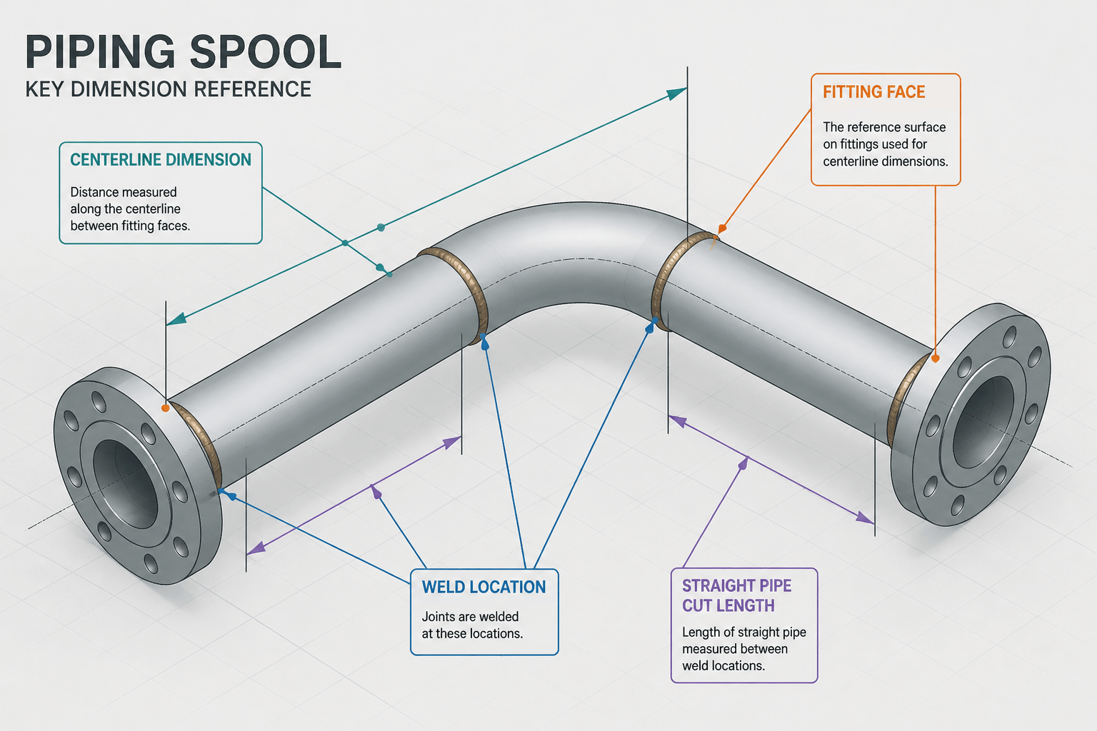
  • Piping Takeoff Dimensions vs. Cut Lengths: Why CAD Measurements Differ

    Piping Takeoff Dimensions vs. Cut Lengths: Why CAD Measurements Differ

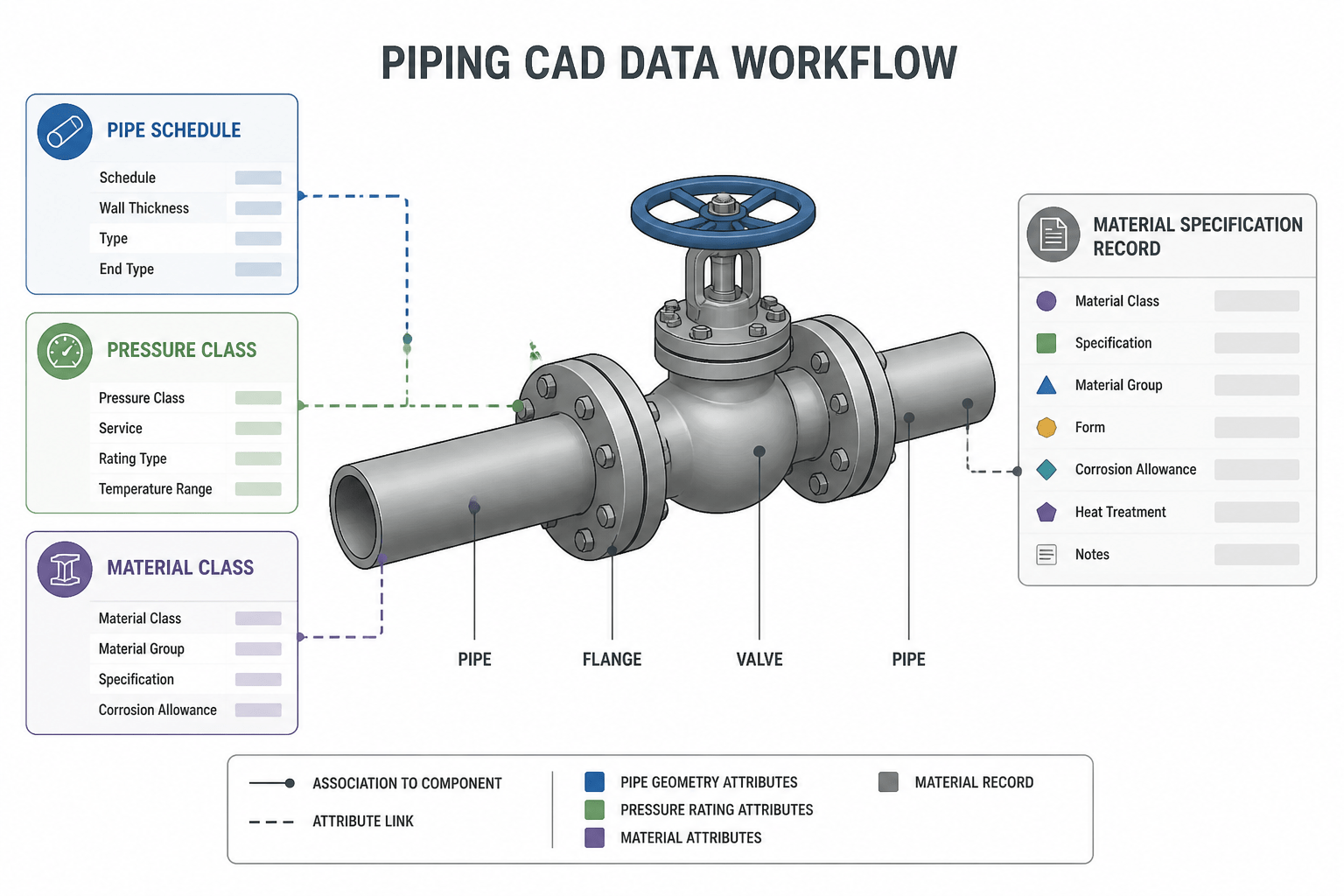
  • Pipe Schedule, Pressure Class, and Material Class in CAD: How to Keep the Data Consistent

    Pipe Schedule, Pressure Class, and Material Class in CAD: How to Keep the Data Consistent

  • Pipe vs. Tube in CAD and Piping Documentation: Terminology, Selection, and Detailing

    Pipe vs. Tube in CAD and Piping Documentation: Terminology, Selection, and Detailing

  • Long-Radius vs Short-Radius Pipe Elbows: How to Read and Detail Them in CAD

    Long-Radius vs Short-Radius Pipe Elbows: How to Read and Detail Them in CAD

  • How to Represent Pipe Wall Thickness and Corrosion Allowance in CAD

    How to Represent Pipe Wall Thickness and Corrosion Allowance in CAD

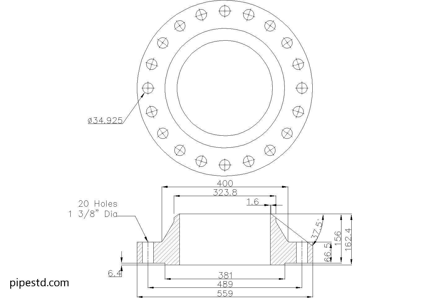
  • Weld Neck Flange 12 Inch Class 600 Dimensions, Weight and Bolt Size

    Weld Neck Flange 12 Inch Class 600 Dimensions, Weight and Bolt Size

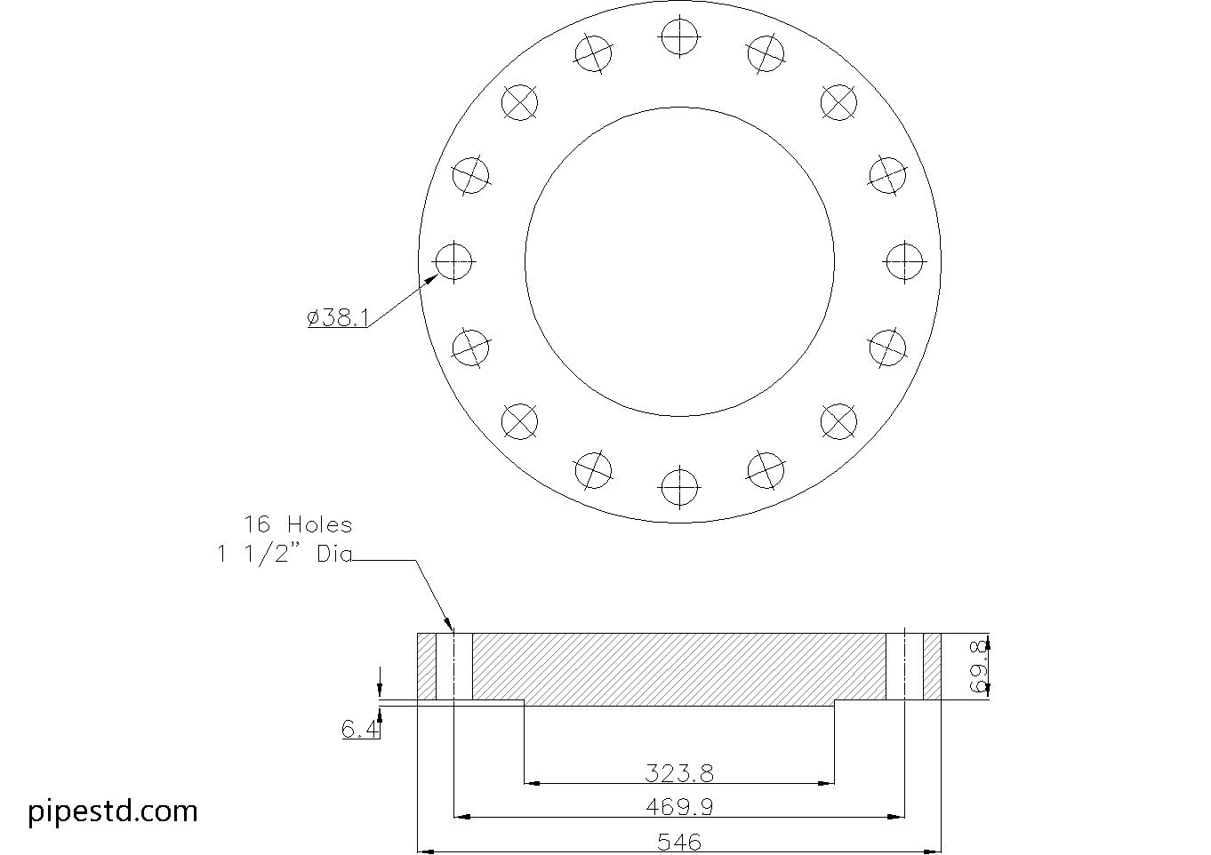
  • Blind Flange 10 Inch Class 900 Dimensions, Weight and Bolt Size

    Blind Flange 10 Inch Class 900 Dimensions, Weight and Bolt Size

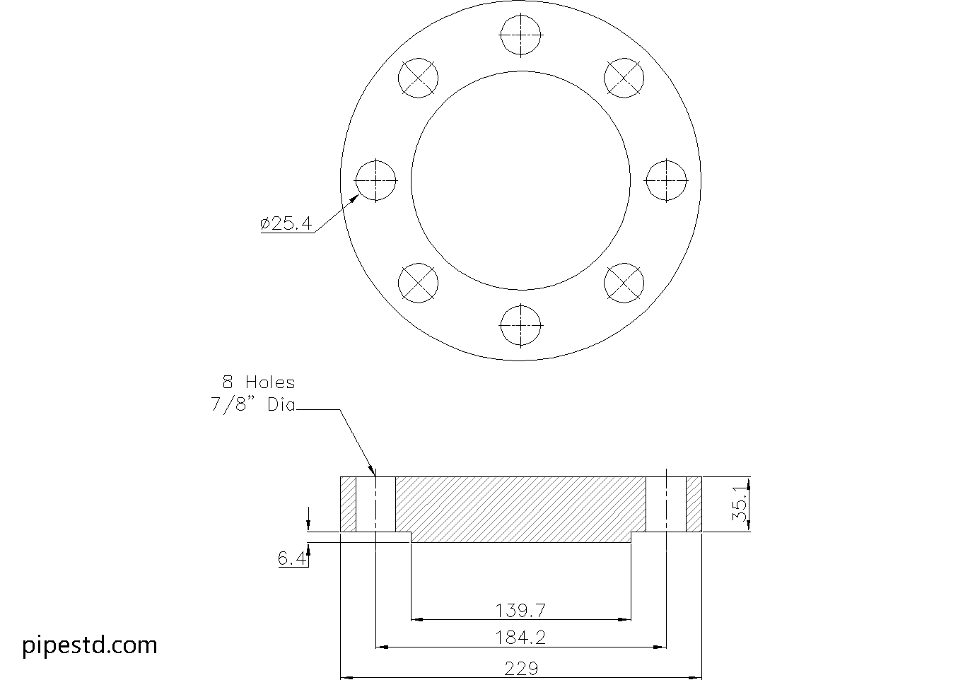
  • Blind Flange 3 1/2 Inch Class 400 Dimensions, Weight and Bolt Size

    Blind Flange 3 1/2 Inch Class 400 Dimensions, Weight and Bolt Size

  • Schedule 40 Pipe 16 Inch (DN400) Dimensions, Weight & Thickness

    Schedule 40 Pipe 16 Inch (DN400) Dimensions, Weight & Thickness