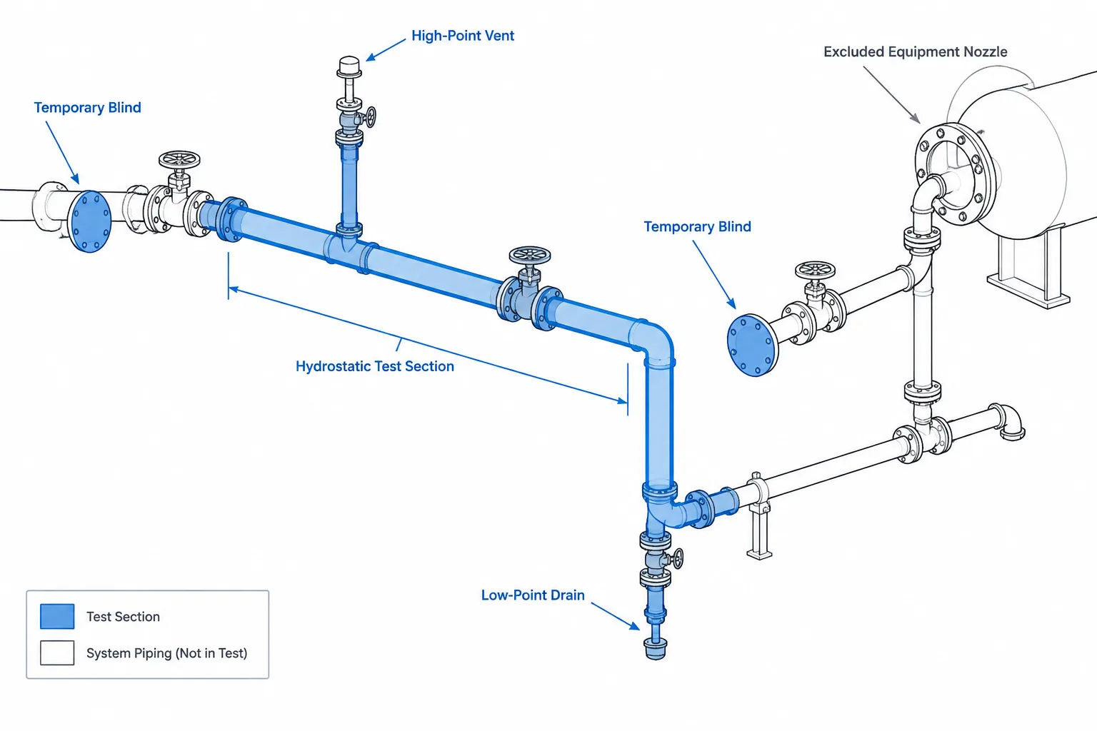
Hydrostatic test boundaries in piping CAD translate an approved testing strategy into a visible, traceable system configuration. The boundary must account for every connected branch, physical isolation point, excluded component, temporary item, vent, drain, and equipment interface—not merely the main piping route.
This guide explains how designers and reviewers can use P&IDs, piping isometrics, layouts, spool drawings, and model information to coordinate test limits with field activities. CAD documentation supports the process, but it does not establish test pressure, component suitability, acceptance criteria, or safe testing methods. Those decisions remain subject to the applicable code, project requirements, approved procedures, and responsible engineering review.
A hydrostatic test boundary defines the portion of a piping system that will be filled, isolated, pressurized, examined, depressurized, and drained as one controlled test section. Although the test pressure and acceptance criteria come from the applicable code, project specification, and approved test procedure, CAD drawings often provide the clearest view of where that test section begins and ends.
Defining a boundary is not as simple as highlighting a line number. A test section may include several line segments, specification breaks, branches, valves, fittings, and temporary connections. It may also stop before equipment, instruments, expansion joints, or other components that are not included in the test. A useful CAD workflow must therefore connect piping geometry with engineering decisions, field isolation methods, and test-package documentation.
What a Hydrostatic Test Boundary Controls
The boundary identifies the physical volume exposed to the approved test conditions. It should answer four practical questions:
- Which permanent piping and components are included?
- Where is the test medium physically contained?
- Which components, instruments, and equipment are excluded or protected?
- Where will filling, venting, pressurization, depressurization, and draining occur?
A highlighted line on a general arrangement drawing may help reviewers understand the overall extent, but it does not by itself establish a field-ready boundary. The isolation devices and temporary closures must also be identified on suitable drawings, such as marked P&IDs, piping isometrics, spool drawings, or dedicated test diagrams.
Permanent and Temporary Boundary Points
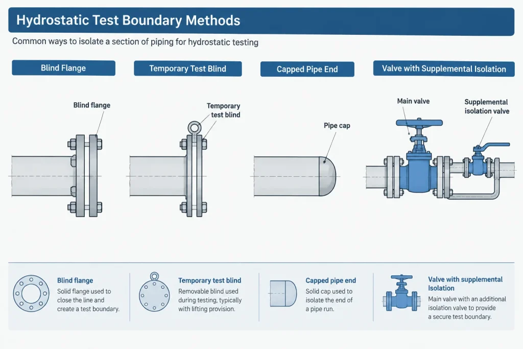
A boundary point is a location where the test volume is physically closed. Depending on the approved test plan, this may involve a permanent piping closure or a temporary test item.
Permanent closures
Permanent closures can include blind flanges, caps, plugs, or other specified end closures. Their suitability cannot be inferred from appearance in a CAD model. The component specification, connection type, pressure basis, installation condition, and test procedure must be verified.
Temporary test blinds and closures
Temporary blinds, test plates, caps, and similar items are commonly used to separate test sections or protect excluded equipment. They should be treated as controlled temporary components rather than generic drafting symbols. Documentation should distinguish them from permanent spectacle blinds, line blinds, and process closures that remain after commissioning.
Where a temporary item is represented in CAD, its tag or identifier should connect it to the test package, installation record, and removal checklist. This helps prevent a temporary closure from being overlooked after testing.
Valves as boundary elements
A closed valve should not automatically be treated as an acceptable test boundary. Leakage across the seat may pressurize an excluded section, and some valve types have cavities or sealing arrangements that require special consideration. The engineering team must determine whether a particular valve may be used for isolation and what additional controls are required.
CAD documentation should show the intended valve position without implying that graphical closure guarantees pressure isolation. If a blind or disconnection is required in addition to the valve, both should be shown.
Components That Need Specific Review
Every component within the highlighted region should be checked against the approved test basis. Particular attention is commonly required at equipment nozzles, instrument connections, check valves, control valves, expansion joints, specialty items, lined components, and piping connected to package equipment.
| Item | CAD and documentation question | Typical coordination concern |
|---|---|---|
| Equipment nozzle | Does the boundary stop at the nozzle, a blind, or another verified point? | A connected vessel or machine may not be part of the piping test. |
| Instrument connection | Is the instrument included, isolated, removed, or replaced by a temporary item? | Instrument pressure limits and trapped volumes require review. |
| Check valve | Is its flow direction and internal closure arrangement understood? | It may obstruct filling, venting, draining, or pressure equalization. |
| Control or specialty valve | What position and protection method are required? | Internal parts may not be intended for the piping test condition. |
| Expansion joint | Is it included, restrained, protected, or excluded? | Pressure thrust and temporary restraint requirements may govern. |
| Package connection | Where does piping responsibility end? | Vendor and site test limits may not coincide. |
This review should be based on verified project documents and supplier information. The CAD model is an organizing tool, not the authority for component test suitability.
High-Point Vents and Low-Point Drains
A liquid-filled test section needs a practical means of releasing trapped air during filling. CAD reviewers should examine the complete test geometry rather than assuming that an existing process vent is located at every relevant high point. Elevation changes, vertical branches, valve bodies, equipment interfaces, and offset routing can create isolated pockets.
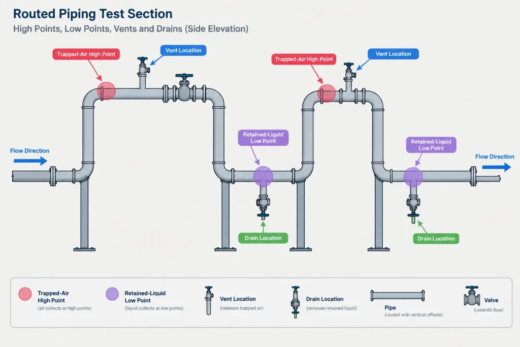
Likewise, the test section should be evaluated for controlled depressurization and drainage. A process drain may not empty every low point created by the test boundary. Temporary hoses or connections may be needed, but their location, discharge destination, and handling method belong in the approved procedure.
For CAD purposes, vents and drains can be classified as:
- Permanent process connections used during testing.
- Permanent connections temporarily adapted for test service.
- Temporary connections installed only for the test.
- Existing openings that require a special valve position or temporary fitting.
Drawings should make this status clear. A temporary vent shown as if it were permanent can create material-list errors, while an unshown temporary connection may lead to field improvisation.
How to Build a Test-Boundary Drawing
A disciplined workflow begins with controlled source documents rather than an isolated copy of the 3D model.
- Confirm the test basis. Obtain the approved line list, piping specifications, test requirements, system limits, and exclusions. Do not calculate or assign test conditions from CAD geometry alone.
- Trace connected piping. Follow every main run and branch within the intended test section. Check small-bore connections, vents, drains, bypasses, sample points, and instrument takeoffs.
- Identify physical limits. Mark every blind, cap, disconnected flange, temporary closure, or approved valve boundary.
- Review included components. Compare valves, instruments, specialty items, and equipment interfaces with the approved test plan.
- Check elevation behavior. Use plans, sections, isometrics, and the model to identify potential air pockets and retained liquid.
- Assign temporary-item identifiers. Give blinds, hoses, pumps, gauges, manifolds, and temporary vents or drains traceable references where required by the project workflow.
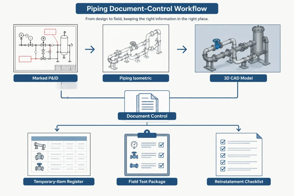
- Reconcile deliverables. Make sure the P&ID markup, isometric highlights, model status, test-package index, and field list describe the same boundary.
Recommended Drawing Information
A test-boundary drawing should remain readable in grayscale, printed form, and electronic review. Color highlighting is useful, but it should be supported by labels, line patterns, symbols, or boundary notes.
Depending on the project procedure, useful drawing information may include:
- A unique test-package or test-section identifier.
- Included line numbers and relevant specification breaks.
- Clearly labeled start and end boundary points.
- Temporary blind and closure identifiers.
- Valve positions required specifically for the test configuration.
- Excluded equipment, instruments, and specialty components.
- Fill, pressurization, vent, depressurization, and drain locations.
- Temporary supports or restraints identified by the responsible discipline.
- References to affected isometrics, P&IDs, and field records.
- A status or revision field showing whether the package is planned, released, tested, reinstated, or closed.
The drawing should not be overloaded with procedural instructions better controlled in the approved test procedure. Its primary job is to define physical scope and provide traceable references.
Reinstatement Is Part of Boundary Control
Hydrostatic testing changes the temporary configuration of a system. Instruments may be removed, valves repositioned, temporary blinds installed, flange joints opened, and temporary connections added. Completion of the pressure hold does not mean the piping is ready for operation.
A reinstatement review should confirm that temporary items were removed, permanent gaskets and components were installed where required, disconnected items were restored, valve positions were reset, and open connections were properly closed. CAD records and test-package markups should be updated to reflect verified field conditions.
Temporary components are especially important because they may not appear in the permanent model or bill of materials. A separate tracked layer, object property, schedule, or test-package register can preserve their visibility without treating them as permanent plant assets.
Common CAD and Coordination Errors
- Highlighting only the main line while missing small branches and instrument connections.
- Stopping the boundary at a closed valve without verifying the isolation method.
- Including connected equipment simply because the pipe model reaches its nozzle.
- Showing fill and drain points but failing to evaluate trapped high points.
- Using color as the only way to distinguish included and excluded piping.
- Leaving temporary blinds or vents without unique identifiers.
- Allowing P&ID, isometric, and field test-package boundaries to diverge after revisions.
- Closing the test package before reinstatement items are verified.
A Boundary Is Both Geometry and Configuration
Hydrostatic test boundaries in piping CAD are most useful when they describe more than a colored region. The drawing must connect physical piping limits, component status, temporary isolation, elevation behavior, and document control. It should also make uncertainty visible: unverified valve isolation, unknown instrument limits, and vendor-package interfaces should be flagged for resolution rather than assumed.
The final boundary and test procedure require approval by the responsible engineering, construction, inspection, and safety organizations. CAD supports that decision by making the test configuration understandable, reviewable, and traceable from planning through reinstatement.
Coordinating the Boundary Across Project Documents
A hydrostatic test package often draws information from several controlled documents. Each document presents a different part of the same test configuration, so agreement among them is essential.
- P&IDs communicate process connectivity, valve relationships, equipment interfaces, and instrument connections.
- Piping isometrics show branch geometry, joints, closures, vents, drains, and locations that may require field action.
- Plans, sections, and the model help reviewers assess elevation changes, access, routing, and potential trapped volumes.
- Test-package records connect the drawing scope to temporary items, inspections, field status, and reinstatement activities.
No single view should be assumed to contain every detail. A boundary that appears complete on a P&ID may still omit a small connection visible on an isometric, while a model may contain geometry without the test-status information needed by the field team.
Use Explicit Status Instead of Graphical Assumptions
Symbols and model appearance can be misread when their test meaning is not stated. A valve symbol does not confirm acceptable pressure isolation, a flange does not prove that a blind is installed, and a modeled vent does not confirm that it serves the actual high point created by the test configuration.
Where the project workflow permits, boundary objects and temporary items should carry clear identifiers and status descriptions. The documentation should distinguish what is permanent, what is temporarily installed, what is excluded, and what still requires verification. This makes unresolved conditions visible during engineering review rather than transferring assumptions to construction or testing personnel.
Boundary Review as a Handoff Check
Before release, reviewers should be able to trace the entire contained volume from one physical limit to the next and follow every connected branch to a verified termination. The same review should identify how air is released, how pressure is controlled, how liquid is removed, and how temporary changes are reversed.
After testing, the package should remain open until required reinstatement actions and field records are verified under the project procedure. This closes the loop between the planned CAD configuration, the test configuration used in the field, and the permanent system configuration.
Frequently Asked Questions
What is a hydrostatic test boundary in piping CAD?
It is the documented physical extent of piping and components exposed to the approved test conditions as one controlled section. The CAD representation should show where that volume is contained, what is included or excluded, and where temporary test provisions are located.
Can a closed valve define the end of a test section?
Not by graphical status alone. The valve design, possible seat leakage, internal cavities, orientation, component limits, and approved isolation method require engineering review. A separate blind, disconnection, or other control may be required by the test plan.
Why must small branches and instrument connections be traced?
They remain connected to the test volume unless physically isolated or removed from the configuration. Missing one can expose an excluded item, create a trapped volume, or leave an unrecognized opening within the package.
Should temporary blinds and vents be modeled as permanent components?
No. Temporary items should be clearly distinguished from permanent plant components while remaining traceable in the test package. Projects may manage them through dedicated layers, properties, schedules, registers, or controlled drawing markups.
Why are both high-point vents and low-point drains reviewed?
Vents support removal of trapped air during filling, while drains support controlled depressurization and removal of test liquid. Actual piping geometry and the temporary test configuration determine whether existing process connections serve those functions.
What is the difference between a test boundary drawing and a test procedure?
The drawing primarily communicates physical scope, isolation points, exclusions, temporary items, and document references. The approved procedure controls the testing method, responsibilities, safety provisions, test conditions, examination, and acceptance requirements.
When is a hydrostatic test package complete?
Passing the pressure test is only part of completion. Required inspections, documentation, drainage, temporary-item removal, component restoration, valve repositioning, connection closure, and reinstatement verification must also be addressed under the project workflow.