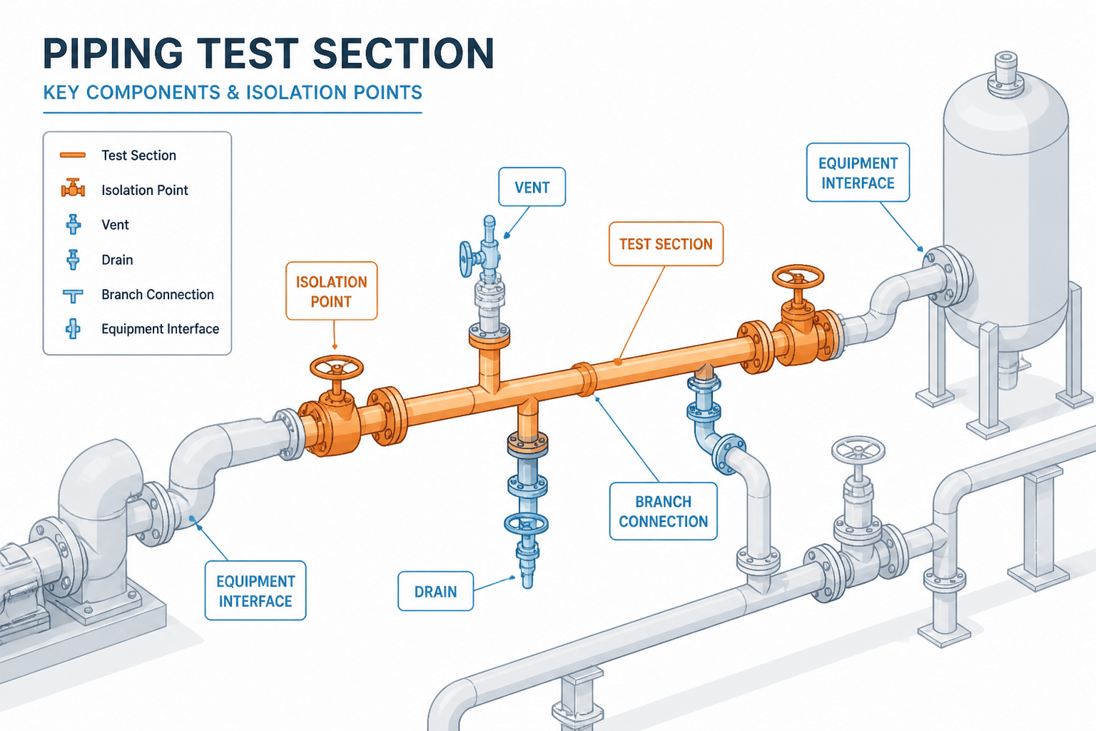
Showing a piping test boundary clearly is a coordination task, not merely a drafting exercise. The CAD representation must connect the approved test scope with the physical isolation points that construction and inspection teams can locate in the field.
This guide explains how to prepare, mark, coordinate, and review test boundaries across piping drawings. It focuses on traceability: every included item, excluded branch, temporary arrangement, and continuation reference should support the same test intent.
Piping test boundaries define which connected components and pipe segments are included in a planned pressure or leak test. In a CAD package, the boundary is more than a highlighted line: it is a coordinated representation of valves, blinds, flanges, vents, drains, instruments, welds, and open ends that must agree with the project’s testing information.
A clear boundary helps designers, drafters, construction teams, and inspectors understand the intended test section. It also exposes coordination problems early, such as a valve shown inside one test section on an isometric but assigned to another section in the line list. The exact test method, acceptance criteria, and allowable pressure are project-specific and should come from the responsible engineering and quality documents.
What a piping test boundary represents
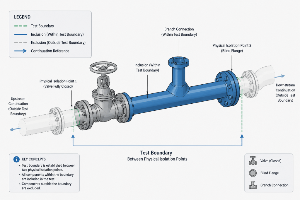
A test boundary is the physical limit of a temporary or permanent piping section being considered for a test. The boundary may be formed by a closed valve, a blind flange, a spectacle blind, a capped connection, a disconnected spool, or another approved isolation point. The drawing should make the intended limit understandable without requiring the reviewer to infer it from unrelated notes.
The boundary has two related parts:
- Included scope: the pipe, fittings, valves, welds, and connected items intended to be tested together.
- Excluded scope: equipment, instruments, branches, hoses, temporary items, or adjacent piping that must remain outside the test section.
In practice, the boundary often crosses several drawing types. A P&ID may show the process isolation concept, an isometric may show the physical break points, a plan or elevation may show access and temporary arrangement, and a line list or test package may identify the administrative test section.
Why test boundaries are difficult to coordinate
Piping drawings are usually developed for multiple purposes. A line number may describe process service, size, material class, and insulation, while a test package divides that line into manageable field sections. A single continuous line may therefore appear in more than one test boundary.
Other complications include equipment nozzles, inline valves, branch connections, small-bore instruments, drains, vents, and piping that crosses drawing sheets. A boundary that appears obvious in a single isometric can become ambiguous when the same point is represented differently on a P&ID, layout drawing, or spool drawing.
CAD users should also distinguish a design boundary from a test boundary. A design boundary may indicate a specification change, battery limit, or ownership division. A test boundary is concerned with how a section will be isolated and verified. The two boundaries can coincide, but they should not be assumed to be identical.
Information to collect before drafting
Before marking a test section, gather the controlling project information rather than starting with a convenient drawing view. The source documents may include a test and inspection plan, piping line list, P&IDs, equipment data, piping material specifications, isometrics, layout drawings, and construction sequencing information.
Check the following items:
- Line number and service description
- Physical limits of the proposed test section
- Isolation points and the type of isolation shown
- Connected equipment and nozzle limitations
- Branch lines that enter or leave the section
- Valves, instruments, hoses, and components that may need removal or protection
- Vents, drains, high points, and low points relevant to filling, draining, or air removal
- Weld or joint identification requirements for the test package
- Temporary blinds, caps, spools, or other field-installed items
If the source documents disagree, do not resolve the conflict by silently changing the CAD drawing. Record the discrepancy and route it through the project’s design clarification or document control process.
How to mark the boundary in a CAD drawing
1. Select a graphic method that is easy to find
Use a dedicated layer, color, linetype, or annotation convention established by the project CAD standard. The boundary should remain distinguishable when the drawing is printed in monochrome or viewed at reduced scale. Avoid relying only on a subtle color change or a line that can be confused with insulation, tracing, demolition, or revision graphics.
A practical presentation often combines a boundary identifier with a visible start and end marker. The identifier should match the test package, isometric notes, or schedule used by the project. Do not create a new numbering system that conflicts with the established document set.
2. Mark physical isolation points, not just abstract limits
Place the boundary marker at the actual isolation location. For a flanged blind, show or reference the flange location. For a valve, identify the valve tag or component position. For a capped branch, show the cap or temporary termination. If the isolation point is off the current sheet, add a clear continuation reference rather than placing the marker near an unrelated component.
Where a valve is used as an isolation point, the drawing should not imply that the valve alone is sufficient for every project condition. The approved test procedure may require additional isolation, removal, or verification. CAD documentation should represent the planned arrangement and identify items requiring field confirmation.
3. Show excluded branches explicitly
Branches are a common source of incomplete test boundaries. A branch that leaves the main run may be included, excluded, or temporarily capped. If it is excluded, show the isolation point or termination and label it consistently. If the branch continues on another sheet, use a continuation reference that makes its relationship to the boundary clear.
Small-bore connections deserve the same review as large process lines. Instruments, sample points, drains, vents, and utility connections can create an unintended open path or an unexamined component within the proposed section.
4. Coordinate the boundary across views
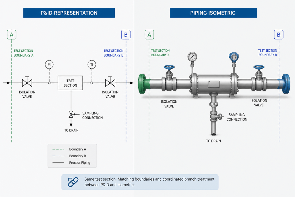
After marking the isometric, compare the same boundary on the P&ID, plan, elevation, and any relevant spool or fabrication drawings. The physical position may be easiest to understand in an isometric, while the process relationship may be clearest on the P&ID. Both views should identify the same isolation intent.
Use a simple cross-check table during review:
| Review item | Question to answer | Typical evidence |
|---|---|---|
| Boundary identity | Does the same test section identifier appear consistently? | Drawing notes, test schedule, line list |
| Physical limits | Can a reviewer locate both ends of the section? | Isometric, plan, equipment connection detail |
| Branch treatment | Is each connected branch included, isolated, or excluded? | P&ID and isometric |
| Component treatment | Are valves, instruments, and equipment connections addressed? | Component tags and test notes |
| Continuation | Do sheet breaks preserve boundary continuity? | Match lines and continuation references |
CAD detailing practices that reduce ambiguity
- Use consistent annotation: Keep the boundary label format, leader style, and marker location consistent across the drawing set.
- Separate temporary work from permanent design: Show temporary blinds, caps, or spool removals with a distinct convention and identify whether they are for construction or testing.
- Preserve component identity: Do not obscure valve tags, flange references, weld numbers, or nozzle labels with boundary graphics.
- Maintain model data: In a 3D plant model, associate the test section with the relevant pipe and component objects where the software supports it. A graphic highlight without usable object data can be difficult to update.
- Check sheet visibility: Confirm that boundary markers, notes, and leaders remain legible at the issued print scale.
- Record open ends: An open pipe end, temporary hose connection, or disconnected spool should be visible or referenced when it affects the test limit.
Common mistakes to catch during review
One frequent mistake is drawing a boundary around a line number without accounting for connected branches. Another is placing a marker at a valve symbol while failing to identify whether adjacent instruments or equipment are included. A third is showing a blind or cap in one view but omitting it from the isometric or field-oriented detail.
Reviewers should also look for boundary labels that stop at a drawing edge, mismatch between P&ID and isometric isolation points, duplicate test identifiers, and notes that describe a component not present in the current revision. If a test section crosses a specification break, ownership limit, or equipment interface, verify that the drawing communicates both relationships without treating them as the same boundary.
A practical final review sequence
- Trace the proposed section from one isolation point to the other.
- Follow every branch, drain, vent, instrument connection, and equipment nozzle encountered along the route.
- Confirm whether each item is included, excluded, removed, capped, or otherwise addressed by the project procedure.
- Compare the physical arrangement with the P&ID and test documentation.
- Check continuation references across sheets and drawing disciplines.
- Verify that temporary items and field actions are clearly distinguished from permanent piping.
- Perform a final print-scale review for marker visibility and note readability.
Well-documented piping test boundaries make CAD drawings more useful during construction and inspection because they connect process intent with a physical, traceable arrangement. The drafter’s role is not to invent the test method, but to represent the approved limits accurately, expose missing information, and keep the boundary consistent across every drawing and schedule that uses it.
How to use this guide during design review
Use the existing project test documentation as the controlling source and use CAD drawings to communicate the physical arrangement. The drawing should help a reviewer answer three practical questions: what is being tested, where the section starts and ends, and how connected items are treated.
For effective review, examine the boundary in both process and physical contexts. Process documentation helps establish the intended isolation relationship, while isometrics and layout views show where blinds, valves, caps, disconnected spools, vents, drains, and other field actions occur. When those views do not agree, the discrepancy should be documented rather than hidden by a drafting assumption.
Important distinction for drafters
A test boundary is not automatically a design limit, material-class limit, ownership limit, or equipment battery limit. These relationships may overlap, but each serves a different purpose. Keeping them distinct prevents a visually convenient boundary from being mistaken for an approved test arrangement.
Before issue, review the boundary as a connected path rather than as an isolated annotation. Trace the piping, inspect every branch and small-bore connection, confirm sheet-to-sheet continuity, and verify that temporary work is recognizable as temporary. This approach makes the drawing more useful to field personnel and gives reviewers a clearer basis for identifying missing information.
Frequently asked questions
What is a piping test boundary in CAD?
It is a documented physical limit that identifies the pipe, fittings, valves, welds, equipment connections, and other items included in a planned test, along with the isolation points and items kept outside the test section.
Should the test boundary be shown on the P&ID or the isometric?
It may need to be coordinated across both. The P&ID commonly communicates process isolation intent, while the isometric or layout drawing usually makes the physical break points easier to locate. The identifiers and isolation intent should remain consistent.
How should an excluded branch be shown?
Show the isolation point, cap, temporary termination, or other approved arrangement and identify the branch consistently. If the branch continues on another sheet, use a clear continuation reference.
Can a closed valve always define the test boundary?
Not automatically. The project test procedure may require additional isolation, removal, protection, or field verification. The CAD drawing should represent the approved arrangement without implying that a valve alone satisfies every project condition.
What should be done when project documents disagree?
Record the discrepancy and route it through the project design clarification or document-control process. Do not silently change the drawing or resolve the conflict through an undocumented drafting assumption.
Why are small-bore connections important in boundary review?
Instruments, sample points, drains, vents, utility connections, and similar branches can create an unintended open path or leave an unexamined component inside the proposed section. They should receive the same boundary review as the main piping.