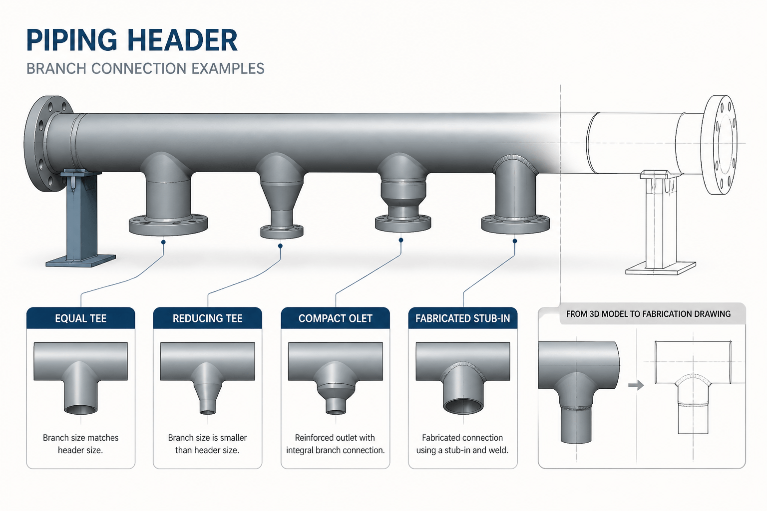
Pipe branch connections are a coordination point between piping layout, component selection, fabrication, and drafting. A branch may appear as a simple intersection in a model, but its actual representation can affect the fitting description, weld documentation, bill of materials, insulation clearance, and review workflow.
This guide compares common branch connection approaches and explains how to carry the selected detail consistently from the piping material specification and line data into the 3D model, isometric, and fabrication documentation. For related terminology, see the reference guides for pipe fittings, pipe dimensions and schedules, and piping isometric drawings.
Pipe branch connections are the points where a branch line leaves a header or run pipe. They may look simple on a piping drawing, but the connection type affects the bill of materials, weld representation, insulation space, support arrangement, and design review process. A branch can be made with a full-size tee, a reducing tee, a forged branch fitting, or a fabricated stub-in connection. These choices should be shown consistently in the model and drawing.
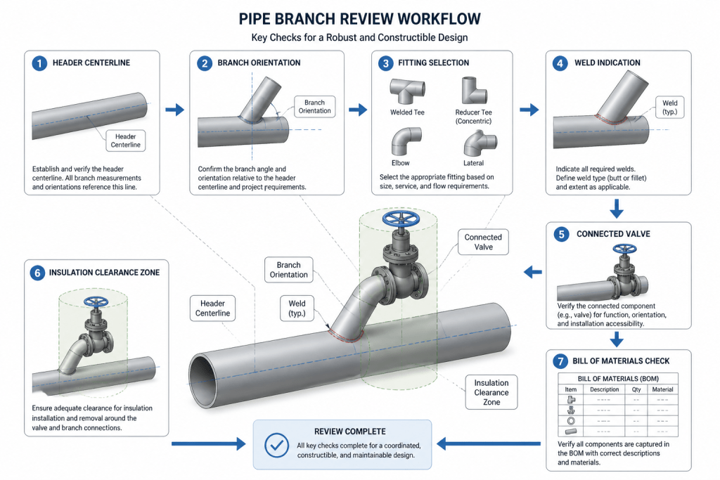
This guide explains the common branch connection types and presents a practical CAD detailing workflow. It is intended to help designers and drafters interpret piping layouts and material specifications. It does not replace project engineering review, piping stress analysis, or the governing piping code.
What is a pipe branch connection?
A pipe branch connection joins a smaller or equal-size branch to a larger pipe called the header, main, or run. The branch may continue to a valve, equipment nozzle, drain, vent, instrument connection, or another piping system.
Branch connections are described by several characteristics:
- Branch orientation: The branch may leave the header at a 90-degree angle, an angled orientation, or another layout direction.
- Branch size: The branch can be the same nominal size as the run or smaller than the run.
- Fitting type: The connection may use a tee, reducing tee, olet, or fabricated pipe connection.
- End connection: The branch end may be butt-welded, socket-welded, threaded, flanged, or connected to a specialized component.
- Reinforcement arrangement: The design may use the fitting body, a formed branch, a reinforcing pad, or another engineered detail.
Do not infer the branch fitting solely from the apparent line size on a P&ID. The piping material specification, line list, project details, and model or isometric information may define the actual component.
Common types of pipe branch connections
Equal tee
An equal tee has a run and branch of the same nominal pipe size. It is commonly used when the continuing pipe and the branch have matching sizes. In a CAD model, the fitting is usually recognizable by three equal connection ends, although the exact geometry may vary by fitting family and manufacturer or project standard.
When detailing an equal tee, verify the orientation of the branch relative to the run. A tee rotated about the pipe axis can appear correct in a simplified plan view while being wrong in the three-dimensional model.
Reducing tee
A reducing tee has a branch or run connection that is smaller than the other connection. It provides a compact transition without modeling a separate reducer and branch arrangement.
Reducing tees require careful size identification. The nominal sizes shown in a component description normally correspond to the run and branch ends in a defined order, but that order should be checked against the project’s component library or material specification. In an isometric, make sure the smaller branch is connected to the intended line and that the bill of materials describes the same configuration.
Branch outlet fittings, or olets
An olet is a branch outlet fitting designed to connect a branch pipe to a larger header. Common families include fittings intended for butt-weld, socket-weld, or threaded branch connections. The names used in project documents may identify the connection style, such as a butt-weld outlet or socket-weld outlet.
Olets are often modeled as compact fittings with a curved or contoured base that follows the header. Their exact external profile is important in CAD because it affects weld representation, insulation clearance, nearby support space, and the visual quality of the fabrication drawing.
Use the project component library where available. A generic block or visually similar fitting can produce incorrect connection points, branch angles, or bill-of-materials data.
Stub-in branch
A stub-in branch is formed by inserting the branch pipe into an opening in the header and welding it according to the approved design detail. Unlike a standard tee or forged outlet fitting, the branch is represented largely by pipe and weld geometry.
Stub-ins can be useful in fabricated piping arrangements, but the required treatment depends on the piping specification, design code, branch size relationship, service, and engineering assessment. The drafter should not add or omit reinforcement based only on visual preference. Show the approved detail, weld symbols, and any reinforcement component required by the project documents.
How to identify the branch connection in project documents
Use more than one source when interpreting a branch. A practical review sequence is:
- Start with the P&ID. Confirm that the branch exists, identify its function, and note valves, instruments, drains, vents, or equipment connections.
- Check the line number and piping class. These identify the governing material and component requirements but do not by themselves prove the exact fitting geometry.
- Review the piping material specification. Look for permitted branch fittings, end connections, material groups, and any project-specific restrictions.
- Inspect the model or isometric. Confirm the actual branch orientation, elevation, weld locations, and connected components.
- Compare the component description with the catalog or reference table. Confirm that nominal size, fitting type, and end connection agree.
A mismatch between these sources should be treated as a design query, not silently corrected in the drawing.
CAD workflow for detailing a pipe branch
1. Establish the header centerline
Draw or model the run pipe first. Confirm its elevation, direction, slope, and relationship to nearby equipment or structural steel. A branch placed on an incorrect header centerline can create errors throughout the isometric.
2. Locate the branch point
Place the branch at the approved station or coordinate. Check whether the branch is centered on a fitting, located at a weld, or connected through a fabricated opening. Avoid moving the branch to improve drawing appearance unless the change is coordinated with the layout.
3. Select the correct component representation
Use the correct tee, reducing tee, outlet fitting, or stub-in detail from the project library. Confirm that connection points and nominal sizes match the line data. If the project uses parametric piping software, verify the component class and end types before generating drawings.
4. Add connected items and check access
Model the branch valve, flange, instrument, drain, or continuation line. Review handwheel access, bolt access, wrench clearance, insulation space, and the ability to fabricate or install the connection. A geometrically valid branch can still create a practical layout problem.
5. Represent welds and reinforcement correctly
Use the project drafting convention for shop welds, field welds, socket welds, branch welds, and reinforcing components. Do not represent a reinforcement pad as a generic ring if the project requires a specific shape, vent hole, material, or attachment detail.
6. Verify the drawing and bill of materials
Check that the fitting appears in the bill of materials with the correct description and quantity. For a stub-in, confirm whether the project counts the branch pipe, reinforcement, and weld detail separately. Review the isometric for disconnected endpoints, duplicate fittings, incorrect weld counts, and inconsistent line-size labels.
Common branch-detailing mistakes
| Mistake | Why it matters | Better practice |
|---|---|---|
| Using a tee symbol for every branch | The drawing may no longer represent the specified component. | Match the symbol and model object to the approved fitting type. |
| Reversing the run and branch sizes | The component description and connected piping can conflict. | Check both connection ends against the line data. |
| Ignoring branch orientation | Valves, drains, instruments, or supports may be placed incorrectly. | Review the branch in plan, elevation, and isometric views. |
| Adding reinforcement without documentation | Unapproved geometry can affect fabrication and material takeoff. | Use the project-approved branch detail or raise a design query. |
| Checking only the centerline model | Clearance and installation problems may remain hidden. | Review outside geometry, insulation, welds, and access zones. |
Final review checklist
- Is the branch shown on the correct header and line number?
- Do the branch and run sizes agree with the piping data?
- Is the fitting type consistent with the piping material specification?
- Are the branch angle, elevation, and orientation correct?
- Are end connections and weld locations identified correctly?
- Are reinforcement, insulation, support, and access requirements addressed?
- Does the bill of materials match the model and drawing?
- Have unresolved differences been documented for engineering review?
Accurate pipe branch detailing depends on coordinating line data, component specifications, 3D geometry, and fabrication requirements. Treat the branch as more than a simple intersection: it is a defined piping component or engineered connection that must remain consistent from the reference table to the final CAD deliverable.
Why branch connection selection matters in CAD
The visible intersection between a header and branch does not always identify the physical component. A tee, outlet fitting, and stub-in can occupy a similar location while requiring different component data, weld treatment, fabrication notes, and material takeoff logic.
For that reason, branch modeling should begin with the project data rather than with a convenient generic symbol. Use the line number, piping class, component library, and approved detail together. When those sources disagree, preserve the discrepancy as a design query instead of making an undocumented drafting assumption.
Related PipeSTD references
- Pipe fittings reference: compare fitting terminology and connection types used in piping documents.
- Pipe dimensions and schedules: verify the dimensional data used by the project’s component and line records.
- Pipe flanges reference: review flange terminology when a branch continues to a flanged valve, instrument, or equipment connection.
- Piping isometric drawings: use the drawing view to check orientation, weld locations, connected items, and material takeoff consistency.
- CAD and DWG pipe resources: support consistent graphical representation while retaining the project-approved component identity.
Practical review principle
A useful branch review follows the information chain: confirm the branch function, identify the governing line and piping class, verify the permitted component, inspect the model geometry, and then reconcile the drawing and bill of materials. This sequence helps separate a drafting issue from a design decision and makes unresolved questions easier for engineering, fabrication, and construction teams to review.
Pipe branch connection FAQ
How do I identify a branch connection type?
Check the piping material specification, component description, model or isometric, and project library together. The apparent shape in a P&ID or simplified CAD view is not sufficient to identify the physical fitting.
What is the difference between a tee and an olet?
A tee is a fitting with defined run and branch connection ends, while an olet is a branch outlet fitting attached to a larger header. The approved project component and end connection determine how each is represented and documented.
When is a stub-in branch used?
A stub-in is a fabricated branch arrangement made from an opening in the header and a branch pipe. Its weld and reinforcement treatment must follow the approved project detail and engineering requirements rather than a drafter’s visual preference.
Should every branch be modeled as a tee?
No. Modeling every branch as a tee can misrepresent the specified component, distort the bill of materials, and hide required weld or reinforcement information. Use the component type defined by the project documents.
Why should branch orientation be checked in multiple views?
A branch can look acceptable in one view while being rotated or positioned incorrectly in the three-dimensional layout. Review plan, elevation, and isometric information along with connected valves, instruments, supports, and equipment.
What should I do when the model and piping specification disagree?
Document the discrepancy and raise it for engineering or project review. Do not silently replace the modeled component or add reinforcement without an approved instruction.