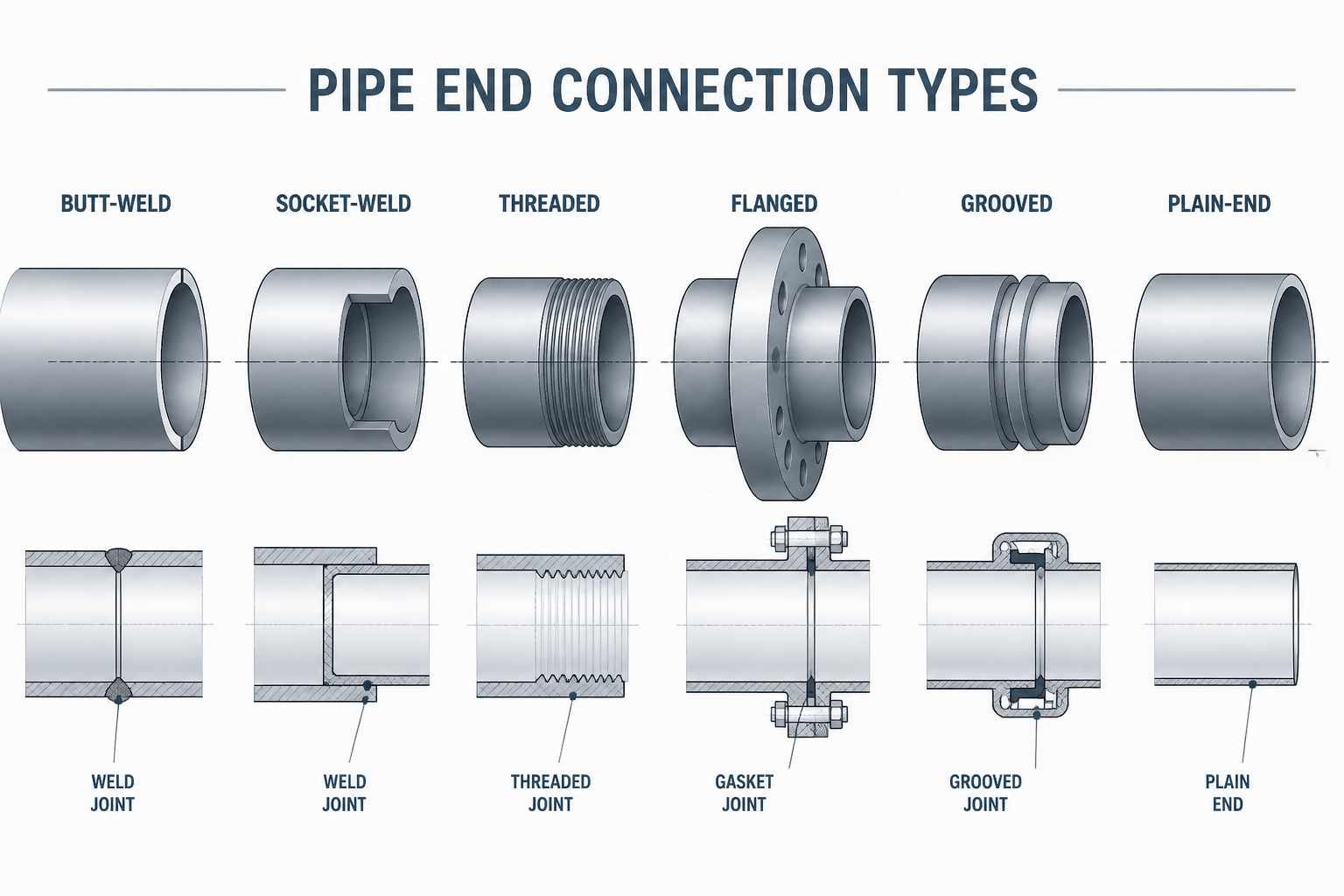
Pipe end connection types are a key part of converting a piping layout into a fabrication-ready CAD document. The connection tells the reader how the pipe meets the next component, what hardware or preparation may be required, and which dimensions must be controlled at the joint.
This reference is useful when reviewing piping isometrics, spool drawings, equipment connections, and bills of materials. Use it alongside the project piping specification and the applicable pipe dimensions and schedules reference. Those resources define the component data; this guide explains how to recognize and communicate the connection itself.
Pipe end connection types determine how a pipe joins to another pipe, fitting, valve, equipment nozzle, or removable component. In a CAD drawing, the connection affects the geometry, fabrication method, bill of materials, inspection notes, and field installation sequence. A line that appears continuous in a model may represent a welded joint, a threaded joint, or a bolted flange connection in the real installation.

For that reason, connection terminology should be established before detailed drafting begins. This guide explains the most common pipe end connections, what they mean in practical drafting work, and how to show them without confusing a nominal pipe size, pipe schedule, fitting type, or pressure class.
Why pipe end connections matter in CAD
A pipe route is not fully defined by its centerline and nominal size. The end preparation and joining method can change the required face-to-face dimension, the fitting selection, the weld representation, and the space needed for assembly or maintenance.
Connection information also travels between documents. A piping material specification may control which end types are permitted for a service or line class. A piping isometric may identify field welds and shop welds. A spool drawing may separate a flanged item from a fabricated welded assembly. Equipment drawings may define the mating connection at a nozzle.
When reviewing a reference table, keep the distinction clear: a dimension table describes a component or pipe product, while the end connection describes how that item joins to the next item. These are related decisions, but they are not interchangeable.
Common pipe end connection types
Butt-weld ends
A butt-weld connection joins two components end to end. The pipe ends are prepared for welding, and the joint is generally represented at the meeting point of the components rather than as a separate bolted or threaded assembly.
In CAD, the most important task is to preserve the correct component length and end condition. A fitting with butt-weld ends may have a different overall length from a similar fitting with socket-weld or threaded ends. Draw the fitting from the correct dimensional reference instead of replacing it with a generic elbow or reducer block.
- Show the component boundary and weld location consistently with the project drawing convention.
- Distinguish a shop weld from a field weld when the fabrication workflow requires it.
- Check whether the pipe end preparation is controlled by the project specification or fabrication standard.
- Do not infer weld details from a line symbol alone if the drawing does not define them.
Socket-weld ends
A socket-weld fitting receives the pipe into a socket or recess before the joint is welded. This connection is common in smaller-bore piping, although the permitted use depends on the project requirements, material specification, service, and applicable engineering rules.
Socket-weld geometry is easy to oversimplify in a CAD block. A symbol that looks like a butt-weld fitting may not communicate the actual insertion relationship. For detailed drawings, use a component representation that identifies the socket connection, particularly when the drawing will support fabrication or inspection.
Pay attention to the insertion depth and the fitting’s dimensional data when creating a spool or assembly. Avoid adding an arbitrary gap or overlap simply to make the drawing look clear. The model should represent the intended connection condition, while fabrication notes should come from the approved project documents.
Threaded ends
Threaded pipe connections use matching internal and external threads. They are often shown at valves, small fittings, instruments, and utility connections, but the acceptable applications vary considerably by material, service, temperature, pressure, and project specification.
In a CAD drawing, a threaded end should not be mistaken for a plain pipe termination. Use the project’s established symbol or annotation convention, and identify the thread information in the bill of materials or component description when required. The drawing may need to distinguish a male threaded end, female threaded end, or a fitting with threaded connections on both ends.
Threaded connections also affect orientation. A fitting that can be assembled by rotation may have different installation implications from a welded fitting. When routing near equipment or other fixed components, leave the access and wrench-clearance requirements defined by the project layout criteria.
Flanged ends
A flanged connection uses two mating flanges with a gasket and bolting. It creates a detachable joint, which can be useful where equipment removal, valve maintenance, or line access is expected. Flange selection involves more than outside diameter: the facing, pressure class, material, bore, bolting, gasket, and mating component must all be coordinated.
In CAD, show the flange as a separate component when the drawing is intended to communicate assembly or bolt-up. A centerline-only piping diagram may use a simplified symbol, but an arrangement drawing or spool drawing should preserve the flange face location and orientation.
- Confirm that the flange face-to-face location matches the selected component data.
- Check flange rotation and bolt-hole orientation where the project requires controlled orientation.
- Coordinate the gasket and bolting descriptions with the bill of materials.
- Review access for tightening, insulation termination, and removal of adjacent items.
For detailed flange work, link the drawing to the site’s applicable flange dimensions and bolt-size reference pages rather than repeating a table inside the drawing note.
Grooved ends
Grooved pipe connections use a groove near the pipe end and a mechanical coupling or related fitting. The coupling provides a detachable joint and may also influence movement, alignment, or installation sequencing.
A grooved connection should be represented as more than a generic break in the pipe. Show the coupling or connection boundary clearly in fabrication and installation drawings. The exact groove profile and coupling requirements should come from the approved component data; do not create a groove detail from visual assumptions.
Plain ends and mechanical connections
A plain end is a pipe termination without a flange, thread, socket, or prepared weld detail being represented at that location. Plain-end pipe may connect through a mechanical coupling, compression fitting, specialized joining system, or field-installed component.
Because “plain end” describes the pipe condition rather than the complete joint, the mating component must be identified separately. In a bill of materials, avoid listing plain-end pipe as though it were a complete connection assembly. The connection hardware, seals, or coupling may require their own item description and procurement information.
How to identify a connection from a drawing
When reviewing an unfamiliar CAD file, use a structured sequence:
- Read the line and component tags. The line number, specification identifier, and item tag may provide more reliable information than the graphic alone.
- Inspect the bill of materials. Look for flange, gasket, coupling, nipple, weld-end, or threaded component descriptions.
- Check the connection symbols and notes. Project legends often define how welds, threads, field joints, and detachable connections are shown.
- Compare mating ends. A flanged valve needs a compatible flange arrangement; a threaded fitting needs the correct mating thread; a socket-weld fitting needs the correct pipe-end relationship.
- Review the governing specification. Confirm that the proposed connection is allowed for the line class and service before treating the drawing as complete.
CAD detailing workflow for pipe connections
Start with the connection inventory
Before modeling, make a short inventory of every termination and joint type in the assembly. Record whether each location is welded, threaded, flanged, grooved, or connected by another specified method. This exposes missing components early and prevents a generic pipe block from hiding an important end condition.
Use component-specific geometry
Build or insert fittings, valves, flanges, and couplings from approved dimensional data. Keep connection points aligned to a consistent insertion or face convention. This is especially important when generating isometrics, extracting spool dimensions, or exchanging models between CAD systems.
Separate graphical clarity from fabrication data
A drawing may use simplified graphics for readability, but the simplification should not remove information needed for fabrication or installation. Use notes, weld identifiers, item balloons, and connection codes where the project drafting standard calls for them.
Perform a mating-end review
Review both sides of every connection. Confirm that the two ends can physically mate, that the required gasket or coupling is present, and that the orientation supports assembly. Also check nearby supports, insulation, access space, and removable items. This review is a coordination check, not a substitute for the project’s engineering or code review.
Common drafting mistakes
| Mistake | Why it causes trouble | Better practice |
|---|---|---|
| Using one generic fitting block for every end type | It hides dimensional and fabrication differences | Use blocks or families that identify the actual connection |
| Leaving threaded or flanged ends unlabeled | The fabricator may not know the intended joint | Apply the project symbol, tag, or component description |
| Ignoring the mating component | A connection may appear complete while hardware is missing | Review both ends and the associated gasket, bolt, or coupling |
| Mixing nominal size with connection size | Similar-looking components may have different connection arrangements | Read size, schedule, end type, and component class together |
Final checklist
- Is every pipe termination assigned a defined connection type?
- Does the CAD geometry match the selected component data?
- Are mating ends compatible and clearly identified?
- Are welds, field joints, flanges, gaskets, threads, and couplings shown according to the project convention?
- Does the bill of materials include the connection hardware required by the design?
- Have the line specification and applicable engineering requirements been checked?
Correctly identifying pipe end connection types turns a visually complete CAD route into a more useful engineering document. The goal is not to add unnecessary detail everywhere, but to make each joint unambiguous to the designer, checker, fabricator, and installer. Use the project specification for final selection, and use dimension and component reference pages to verify the geometry of the parts being modeled.
How connection terminology fits with other piping data
A pipe description can contain several separate pieces of information. Nominal size identifies the intended size designation, schedule describes a pipe wall category, and the component description identifies the fitting, valve, flange, or other item. The end connection states how that item joins to the next component. Keeping these categories separate helps prevent incorrect CAD blocks, incomplete bills of materials, and mismatched mating parts.
When checking a model, follow the connection from one component to the next rather than reviewing each item in isolation. A flange may require a matching flange, gasket, and bolting. A threaded fitting may require compatible thread directions or end descriptions. A coupling may need to be modeled as a separate item even when the pipe appears continuous in the layout.
Useful PipeSTD references for connection review
- Use the pipe dimensions and schedules reference to verify the pipe representation independently from its joining method.
- Use flange dimensions and bolt-size references when checking flange face locations, orientation, and associated hardware.
- Use the pipe fittings reference to compare fitting types and component-specific geometry.
- Use the piping terminology guide when a drawing uses abbreviations or connection codes that need clarification.
- Use the CAD and DWG resources to keep blocks, connection points, and drafting conventions consistent across drawings.
Connection review versus design approval
A CAD review can identify missing connection information, incompatible-looking mating ends, and coordination problems. It does not by itself approve a connection for a particular service or project. Final selection should be checked against the approved line class, project documents, equipment requirements, and applicable engineering review.
Frequently asked questions
What is a pipe end connection type?
A pipe end connection type describes how a pipe or component joins to the next item. Common examples include butt-weld, socket-weld, threaded, flanged, grooved, and plain-end arrangements.
Is a pipe end connection the same as pipe schedule?
No. Pipe schedule and connection type describe different aspects of a piping item. Schedule relates to the pipe wall designation, while the connection type describes the joining arrangement at the end.
How should pipe end connections be shown in CAD?
Use the project’s approved symbols, component geometry, tags, and notes. The level of detail should match the drawing purpose: a schematic may be simplified, while a spool or fabrication drawing should communicate the relevant face locations, joint boundaries, and hardware.
Why must mating ends be checked together?
A connection is an interface between two components. Checking only one side can hide a missing flange, gasket, coupling, compatible thread, or required weld relationship.
Should every plain pipe end be treated as a complete connection?
No. “Plain end” describes the condition of the pipe termination, not necessarily the complete joint. The mating fitting, coupling, seal, or other connection hardware should be identified separately when required.
Where should flange geometry be verified?
Verify flange geometry against the approved component data and the applicable PipeSTD flange dimensions reference. Coordinate the result with the project specification, mating component, gasket, bolting, and drawing convention.