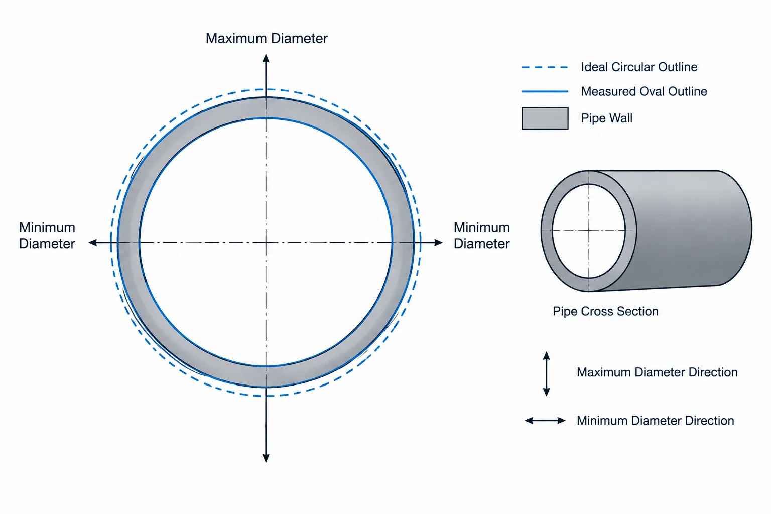
Pipe ovality and out-of-roundness describe cross-sectional variation that nominal piping models usually do not represent. The distinction becomes important when actual pipe shape controls weld fit-up, coupling engagement, sleeve clearance, liner insertion, bend geometry, or an equipment connection.
This reference explains how the condition differs from outside-diameter tolerance, how measurements should be recorded, and how designers can manage the difference between ideal CAD geometry and measured field geometry.
Pipe is normally represented in CAD as a straight circular cylinder, but real pipe is not perfectly round. Manufacturing, handling, forming, welding, bending, heat treatment, transport, and installation can all produce some difference between the largest and smallest measured diameters. This condition is commonly described as pipe ovality or out-of-roundness.
Small departures from a perfect circle may have little effect on an ordinary run of pipe. At welded joints, close-fitting components, bends, lined systems, mechanical couplings, and equipment interfaces, however, cross-sectional shape can become an important fit-up issue. Designers and drafters need to understand the distinction between nominal CAD geometry and the actual shape that fabrication personnel may encounter.
What Pipe Ovality Means
Pipe ovality describes a cross section in which the measured diameter is not the same in every direction. When measured across several axes, one direction may produce a maximum outside diameter while another produces a minimum outside diameter.
A truly oval cross section resembles an ellipse, but the term is also used more generally for pipe that is out of round. Actual pipe may have local flats, weld-related distortion, dents, or irregular curvature rather than a smooth elliptical shape. For that reason, ovality and out-of-roundness may be treated differently in a project specification or inspection procedure.
The following terms should not be confused:
- Outside diameter tolerance: The permitted variation of an outside-diameter measurement from its specified value.
- Ovality or out-of-roundness: The difference between diameters measured in different directions at the same cross section.
- Wall-thickness variation: A change in wall thickness around the circumference or along the pipe.
- Eccentricity: A condition in which the inside and outside surfaces do not share the same center.
- Dent: A localized inward deformation rather than a general difference between major and minor diameters.
A pipe can satisfy an average outside-diameter requirement yet still present a noticeable difference between its maximum and minimum diameters. Conversely, a nearly circular pipe can have a diameter that is uniformly different from the intended value. These are separate dimensional conditions and should be evaluated using the applicable purchase specification, material standard, fabrication procedure, or project requirement.
How Out-of-Roundness Is Measured
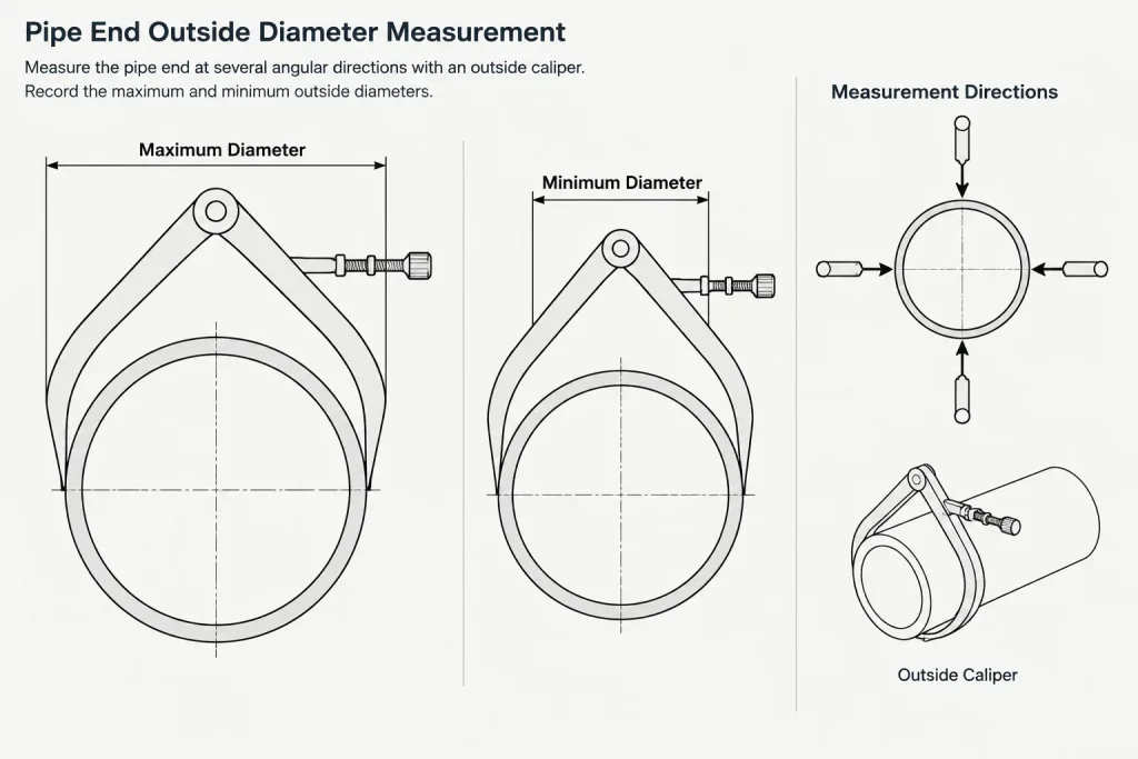
A common field or shop approach is to measure the outside diameter in multiple directions at a selected cross section. At minimum, measurements are typically taken across two axes, but additional readings provide a better picture when the shape is irregular.
The maximum measured diameter and minimum measured diameter can then be compared. Some procedures express their difference directly. Others calculate ovality as a percentage using a specified reference diameter. Because calculation conventions are not universal, a drawing or inspection report should not state only an unexplained percentage. It should identify the governing definition or procedure.
Common measurement methods
- Outside calipers or diameter-measuring tools: Useful for checking diameters across selected axes where the full circumference is accessible.
- Diameter tape: Measures circumference and converts it to an equivalent diameter. It is useful for overall size checks but may not reveal maximum and minimum diameters by itself.
- Templates or go/no-go gauges: Used for particular fabrication or fit-up checks when a controlled envelope is required.
- Internal gauges: Used when bore shape matters and the inside surface is accessible.
- Laser scanning or dimensional survey: Can capture a more complete cross-sectional profile for critical interfaces or deformation investigations.
Measurements should be taken at a clearly identified location. Results near a pipe end, bend tangent, longitudinal seam, girth weld, forming transition, or damaged area may differ from those in an unaffected straight section. A useful inspection record therefore includes both the measured values and their axial and circumferential locations.
Why Ovality Matters During Fit-Up
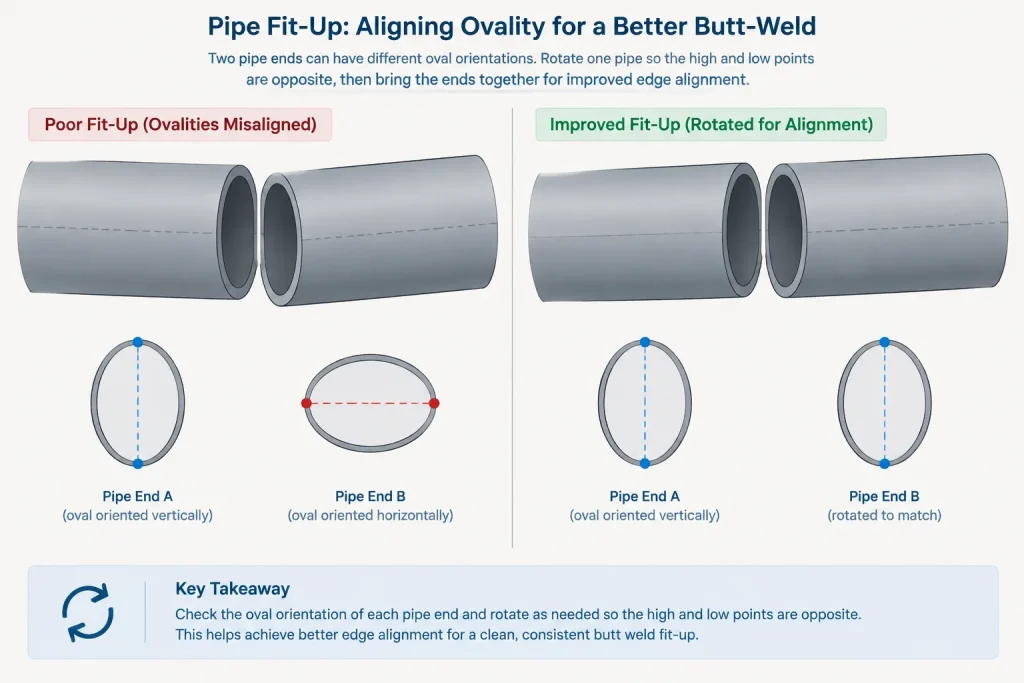
Many piping joints require two circular parts to align closely enough for assembly, welding, sealing, or coupling engagement. If one or both parts are out of round, their nominal centerlines may align while their actual edges do not.
| Interface | Possible effect of out-of-roundness | Typical control approach |
|---|---|---|
| Butt-welded pipe ends | Uneven internal or external mismatch around the joint | Measure, rotate for best fit, reform where permitted, and verify weld preparation |
| Pipe-to-fitting weld | Local high and low points at the mating edges | Check both components rather than assuming the fitting is perfectly round |
| Mechanical or grooved coupling | Difficulty seating the housing or gasket consistently | Verify the coupling manufacturer’s dimensional and end-preparation requirements |
| Close-fitting sleeve or clamp | Interference at the major diameter or gaps at the minor diameter | Check the actual external envelope and required contact condition |
| Internal liner or insert | Restricted insertion, uneven clearance, or local liner stress | Control the bore profile and inspect the receiving pipe |
| Equipment nozzle connection | Forced alignment or uneven weld fit-up | Survey the actual interface and avoid using bolting or welding to hide misalignment |
Rotating one pipe relative to another may improve alignment because the major and minor axes can be positioned more favorably. This is a fit-up technique, not a substitute for acceptance criteria. Any reforming, jacking, heating, or mechanical correction must follow the approved fabrication procedure and applicable material controls.
Ovality in Bends and Formed Components
Pipe bending can change a circular cross section. The bend may flatten, with one diameter increasing while the perpendicular diameter decreases. The amount and distribution depend on the forming process, bend geometry, tooling, pipe wall, material behavior, and fabrication controls.
This matters for more than appearance. Cross-sectional distortion may affect:
- Clearance through closely spaced structures or sleeves;
- Insertion of cleaning tools, inspection devices, or internal components;
- Attachment of clamps, shoes, wear pads, or external reinforcements;
- Matching a bend end to adjoining straight pipe or fittings;
- Flow-area calculations when deformation is significant;
- Inspection and acceptance under the project’s governing requirements.
A standard CAD elbow or swept bend generally retains a perfectly circular section throughout its geometry. It communicates routing and nominal envelope, but it does not predict fabrication-induced flattening. Where the actual formed shape controls clearance or internal passage, verified fabricator information is needed.
What CAD Models Do and Do Not Show
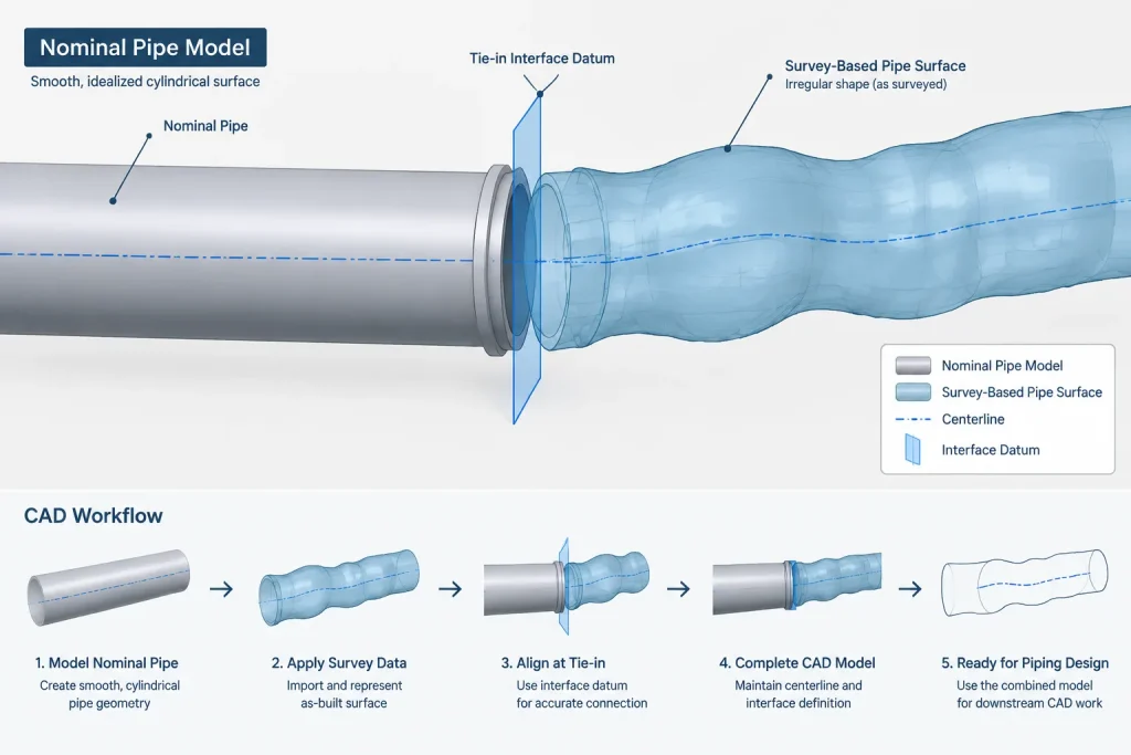
Most piping models use nominal geometry. A pipe component is created from a nominal size, selected wall designation, and database outside diameter. The software then represents it as an ideal cylinder with a concentric bore. That approach is appropriate for normal plant layout, interference checking, isometric generation, and material reporting.
Modeling every permissible manufacturing variation would make the model difficult to manage and could imply knowledge that the designer does not have. The usual goal is therefore not to distort ordinary CAD components. Instead, the project should identify interfaces where actual shape must be confirmed.
Situations that may require more than nominal geometry
- A large fabricated or formed pipe section passing through a tight opening;
- A replacement spool connecting to surveyed existing pipe;
- A repair clamp, sleeve, or split fitting designed around measured geometry;
- A close-clearance internal device;
- A tie-in where existing pipe ends are known to be deformed;
- A failure investigation or as-built deformation survey.
For these cases, a scan-based or survey-based representation may be kept separately from the nominal design model. The file and drawing should clearly distinguish measured existing geometry from nominal new-component geometry. Otherwise, later users may treat a survey mesh as a specified fabrication shape or assume that a nominal cylinder records field conditions.
Drawing and Documentation Practices
General arrangement drawings and standard isometrics usually do not need an oval pipe symbol. If ovality affects fabrication or installation, communicate it through controlled notes, inspection records, detail drawings, or interface data.
Useful documentation may include:
- The cross section or station where measurements were taken;
- Maximum and minimum measured outside or inside diameters;
- The orientation of those measurements relative to a known datum;
- Whether the readings apply to the pipe body, end preparation, bend, or welded area;
- The measurement method and inspection procedure;
- Whether values are design limits, purchase requirements, or field observations;
- Required action before welding, coating, lining, or assembly.
Avoid notes such as “make round” unless the fabrication method, acceptance basis, and responsible party are defined elsewhere. Likewise, do not assign a generic ovality limit from memory. Permitted variation can depend on the product form, material specification, manufacturing method, service, joint type, and project requirements.
A Practical CAD and Fit-Up Workflow
- Model nominally. Use verified component dimensions for routine layout and material control.
- Identify shape-sensitive interfaces. Flag sleeves, clamps, liners, tie-ins, close-clearance passages, and formed pipe sections.
- Define the needed information. Decide whether nominal diameter, circumference, maximum and minimum diameters, or a complete scanned profile is required.
- Obtain measured or vendor data. Do not infer actual ovality from a generic CAD component.
- Check fit and clearance. Evaluate the controlling envelope and bore, not merely the modeled centerline.
- Document the basis. State whether geometry is nominal, measured, or based on supplier information.
- Preserve field responsibility. Require verification where installation depends on conditions that cannot be established during design.
Key Takeaway
Pipe ovality is a cross-sectional shape issue, not simply another name for outside-diameter tolerance. It can affect weld mismatch, coupling assembly, sleeves, liners, bends, repairs, and equipment interfaces even when the CAD model appears perfectly aligned. Routine piping models should normally remain nominal, while shape-sensitive connections should be supported by appropriate measurements, inspection criteria, and clearly identified as-built information.
Turning Measurements Into a Usable Fit-Up Record
A maximum and minimum diameter can indicate that a cross section is out of round, but those readings alone may not fully describe the assembly problem. Fit-up personnel also need to know where the section was measured and how its major and minor directions relate to a physical datum, weld seam, bend plane, or installation orientation.
Orientation matters because rotating a component can change where interference, mismatch, or clearance occurs. A useful record connects the dimensional findings to a repeatable reference so that engineering, fabrication, inspection, and field teams are discussing the same condition.
Questions to resolve before accepting or correcting the condition
- What is being evaluated? Distinguish the pipe body, prepared end, bend, weld area, fitting, sleeve, liner, or mating component.
- Which surface controls? An outside envelope may govern a clamp or opening, while the bore may govern an insert or inspection device.
- Is the geometry nominal or measured? Clearly identify whether information comes from the design model, supplier data, shop inspection, or a field survey.
- What requirement governs acceptance? Use the applicable material, purchase, fabrication, joint, equipment, or project criteria rather than a generic rule.
- Who may authorize correction? Reforming or other corrective work should follow an approved procedure and the applicable material controls.
Managing Nominal and Surveyed Geometry
Nominal CAD geometry and surveyed geometry serve different purposes. The nominal model supports routing, component selection, drawing production, and material management. A survey model records an observed condition at a particular location and time. Combining them without clear identification can create false precision or cause measured deformation to be mistaken for a fabrication requirement.
When both are needed, use clear model naming, status information, and drawing notes. Identify the source of the surveyed geometry and the interface for which it was obtained. The design team should also state whether a clearance review used the external envelope, internal passage, mating edge, or another controlling feature.
Practical review sequence
- Confirm the governing interface and the surface that controls fit.
- Review the measurement location, method, orientation, and equipment used.
- Compare both mating parts where assembly depends on their combined shape.
- Evaluate the actual envelope or bore rather than relying only on centerline alignment.
- Record any approved orientation, correction, or field-verification requirement.
- Keep acceptance records linked to the affected component or joint.
This approach allows routine piping to remain efficient in CAD while giving shape-sensitive interfaces the additional dimensional control they require.
Frequently Asked Questions
Are pipe ovality and outside-diameter tolerance the same?
No. Outside-diameter tolerance concerns variation from a specified diameter, while ovality concerns differences between diameters measured in different directions at the same cross section. A pipe may present one condition without the other.
Can a diameter tape determine the maximum and minimum diameters?
A diameter tape is useful for circumference-based size checks, but it may not identify directional maximum and minimum diameters by itself. The inspection method should match the shape information required.
Should an out-of-round pipe be modeled as an ellipse?
Not routinely. Standard piping models generally use ideal circular geometry. An elliptical or scan-based representation is more appropriate when measured shape directly controls a repair, tie-in, internal passage, or close-clearance interface.
Does an oval cross section always have a smooth elliptical shape?
No. Actual deformation may include local flats, dents, seam-related distortion, or irregular curvature. Maximum and minimum diameter readings may therefore be insufficient for a critical interface that depends on the complete profile.
Can rotating a pipe solve a fit-up problem?
Rotation may improve the relationship between the major and minor directions of mating components, but it does not establish acceptance. The completed joint must still satisfy the governing requirements and approved fabrication procedure.
What should a pipe ovality inspection record include?
It should identify the component, measurement station, measured surface, maximum and minimum directions, orientation datum, measurement method, relevant procedure, and whether the information represents an observation or an acceptance limit.
When is laser scanning or dimensional surveying useful?
Detailed surveying can be useful when a complete profile is needed for a deformed tie-in, repair component, restricted opening, internal device, or investigation. The resulting geometry should be clearly distinguished from the nominal design model.