
Pipe wall thickness values serve different purposes across design, procurement, fabrication, CAD, and inspection. A value taken from a schedule table does not represent the same engineering decision as a calculated requirement or a field measurement.
This guide explains how to identify each thickness term, trace it to the controlling document, and avoid using one value as a substitute for another.
Pipe wall thickness can appear to be a single, straightforward value. In practice, designers, manufacturers, inspectors, and CAD users may be referring to several different values: the thickness listed for a pipe schedule, the minimum thickness required by a design calculation, the ordered nominal thickness, or the wall actually measured in the field.
Those values are related, but they are not interchangeable. Confusing them can lead to incorrect inside diameters, unsuitable material selections, misleading CAD geometry, or faulty remaining-life assessments. The first step is to identify what a thickness value represents and which document controls it.
The Main Pipe Wall Thickness Terms
| Term | Practical meaning | Typical use |
|---|---|---|
| Nominal wall thickness | The designated thickness used to order, identify, or describe the pipe. A schedule table commonly provides this value for a given nominal pipe size. | Specifications, purchase descriptions, catalogs, piping classes, and CAD component data |
| Minimum required thickness | The calculated thickness needed to satisfy the applicable design basis after considering the required conditions and code methodology. | Engineering calculations and pipe thickness selection |
| Ordered thickness | The nominal wall thickness stated in the purchase requirement. It may be a schedule-based thickness or another permitted product thickness. | Procurement and material control |
| Actual or measured thickness | The physical wall thickness found at a particular location on manufactured or installed pipe. | Receiving inspection, quality control, and in-service examination |
| Remaining thickness | The measured wall still present after service-related loss, damage, or other degradation. | Inspection and integrity assessment |
| Retirement or minimum allowable thickness | A project- or assessment-defined threshold used to determine whether continued service is acceptable. | Mechanical integrity programs and repair planning |
Terminology can vary among companies and governing documents. A note saying only “minimum wall” is therefore incomplete unless its calculation basis and intended use are clear.
What Nominal Wall Thickness Means
Nominal wall thickness is the reference thickness associated with the specified pipe product. When a pipe is identified by nominal pipe size and schedule, the schedule designation leads to a listed nominal wall thickness for that size.
Schedule is not itself a universal physical thickness. The same schedule designation can correspond to different wall thicknesses at different nominal pipe sizes. Conversely, different schedule designations may occasionally lead to the same listed wall for particular sizes. The schedule and nominal size must be considered together.
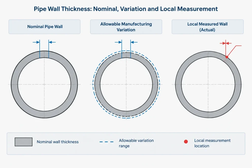
The word nominal is important. Product specifications generally recognize manufacturing variation, subject to the applicable acceptance limits. A pipe ordered at a nominal wall is not expected to have that exact thickness at every point around its circumference and along its length.
Minimum Required Thickness Is a Design Result
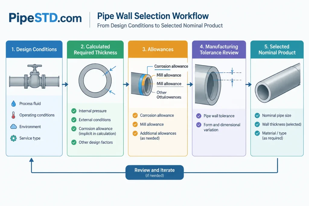
Minimum required thickness is normally developed from an engineering calculation rather than read directly from a schedule table. Its basis may include internal or external pressure, temperature, material strength parameters, joint or quality factors, mechanical loads, allowances, and other conditions required by the governing design rules.
The precise calculation method depends on the applicable code, service, material specification, and project criteria. A schedule should not be selected by comparing its listed wall to a simplified pressure-only result without checking the complete design basis.
A common selection process is:
- Establish the governing design conditions and material basis.
- Calculate the structural or pressure-design thickness using the applicable method.
- Apply corrosion, erosion, threading, grooving, or other allowances where required.
- Account for permissible negative manufacturing tolerance when the governing method requires it.
- Select an available nominal wall thickness that satisfies the resulting requirement.
- Check any additional loads, fabrication effects, and project-specific limits.
This is a workflow, not a universal equation. Different rules may incorporate allowances and tolerances at different stages, so calculation terminology should follow the controlling engineering procedure.
Why Ordered Wall Can Be Greater Than the Calculated Minimum
The exact calculated thickness is often not a standard purchasable pipe wall. The engineer typically selects the next suitable available nominal thickness that complies with the material specification and piping class.
The difference between the selected nominal wall and the calculated minimum should not automatically be treated as extra corrosion allowance or unrestricted design margin. Part of that difference may be needed to accommodate manufacturing tolerance, and the project may have additional selection rules. A piping class may also standardize one heavier wall across several lines to simplify procurement, welding, stocking, or maintenance.
Measured Thickness Is Local, Not Universal
A field thickness reading describes the pipe at the measurement location. It does not, by itself, establish the minimum wall around the full circumference or along the entire component.
Readings may be influenced by surface condition, coating, instrument setup, calibration, geometry, accessibility, and operator technique. Localized corrosion can also exist between measurement points. Inspection plans therefore use an appropriate pattern, repeatable locations, and evaluation procedure rather than relying on one isolated reading.
Measured wall should be compared with the correct assessment threshold. Comparing it only with the original nominal wall can show apparent material loss, but it does not by itself determine fitness for continued service. That decision requires the applicable integrity method, current conditions, and qualified engineering review.
How Wall Thickness Affects Inside Diameter
For a simple nominal CAD cylinder, inside diameter is often represented as outside diameter minus twice the nominal wall thickness. This is useful for reference geometry, interference studies, and approximate flow-area calculations.
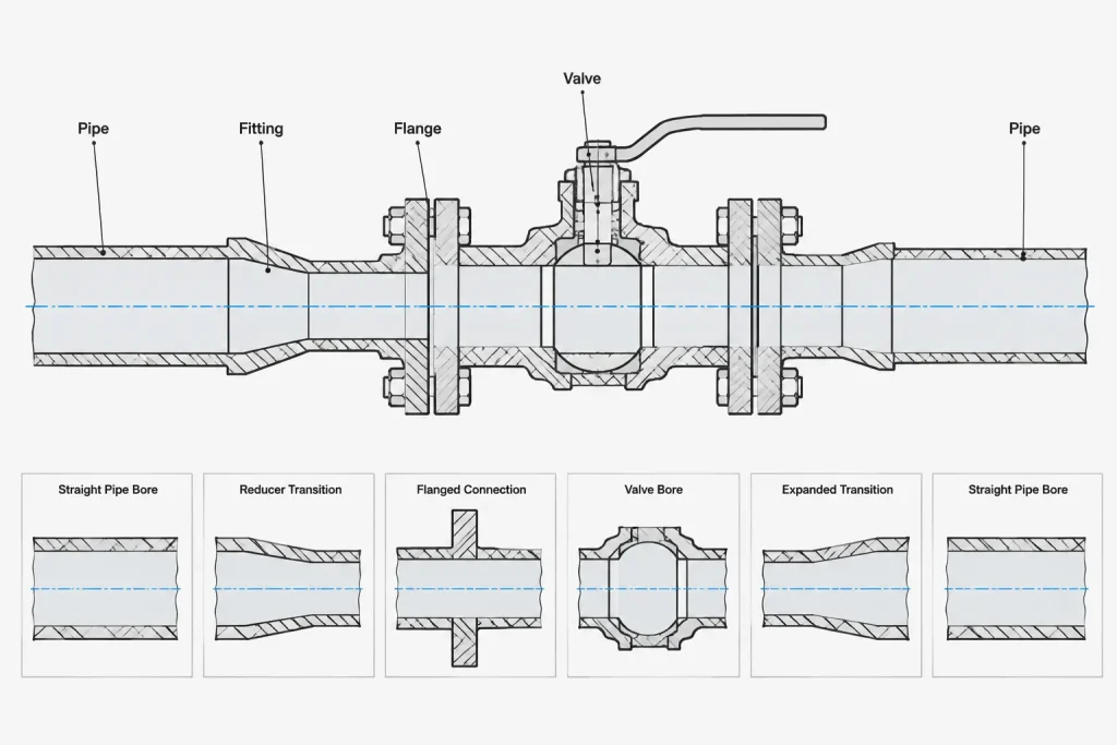
However, that derived bore is a nominal model value. Real pipe may include wall variation, ovality, weld-seam geometry, lining, deposits, corrosion, or fabrication transitions. The minimum actual bore is therefore not guaranteed merely by subtracting the listed wall from the nominal outside diameter.
This distinction matters when bore clearance is critical, such as for internal tools, close-fitting inserts, lined components, or connections with significant internal mismatch. In those cases, verified product and fabrication data are more appropriate than generic schedule geometry.
How to Represent Wall Thickness in Piping CAD
Use nominal dimensions for generic pipe geometry
A standard piping model normally represents the specified nominal outside diameter and wall thickness. Modeling random manufacturing variation would add complexity without improving ordinary layout coordination.
Keep engineering requirements in data, not hidden geometry
The model or associated line data should retain the pipe specification, nominal size, schedule or ordered wall, material, and other controlled attributes. A minimum required thickness calculation should remain traceable to its engineering document rather than being inferred from a modeled solid.
Do not use CAD measurements as inspection evidence
Measuring a modeled pipe wall confirms only the geometry created in the file. It does not establish the wall delivered by a manufacturer or remaining in an operating system.
Identify special bores explicitly
If a component has a machined bore, lining, overlay, taper, or project-specific transition, distinguish that geometry from generic schedule-based pipe. Add the controlling note, component data, or vendor reference needed to prevent the nominal model from being mistaken for verified fabrication geometry.
A Practical Document Review Workflow
- Start with the line list and piping class: Confirm nominal size, material, schedule or wall designation, service, and specification break locations.
- Check the thickness calculation: Verify which value is the calculated requirement and whether allowances and manufacturing tolerance have been addressed.
- Check product availability: Confirm that the selected wall is available under the intended material and product specification.
- Reconcile the CAD model: Make sure modeled wall data and component ports match the selected nominal pipe description.
- Review connected components: Examine valve bores, flange bores, fitting ends, branch connections, and other potential internal transitions.
- Separate design from inspection data: Store field readings, examination locations, and remaining-thickness evaluations in the appropriate integrity records.
- Resolve ambiguous notes: Replace unsupported labels such as “minimum wall” with terminology that identifies the value’s purpose and source.
Common Interpretation Errors
- Treating a schedule number as though it were a wall thickness.
- Assuming nominal thickness exists exactly and uniformly throughout the pipe.
- Selecting a schedule directly from a pressure calculation without accounting for the full design method.
- Calling all thickness above the calculated requirement corrosion allowance.
- Using a nominal CAD bore as a guaranteed minimum passage.
- Comparing inspection readings with nominal wall when a different assessment threshold controls.
- Using “minimum,” “actual,” and “nominal” interchangeably in calculations and drawing notes.
The Key Distinction
Nominal wall thickness describes the specified pipe product, minimum required thickness comes from an engineering basis, and measured thickness describes physical material at a particular location. Schedule tables help identify nominal products, but they do not replace design calculations, manufacturing requirements, or inspection assessments.
Keeping these values separate makes piping specifications clearer, CAD models more reliable, and inspection comparisons easier to interpret. Whenever a wall-thickness value appears, the practical question is not simply “How thick is the pipe?” but “Which thickness value is this, and what decision is it intended to control?”
Record the Value and Its Basis Together
A wall-thickness entry is most useful when its type, source, and purpose are recorded together. For example, a nominal wall may come from the selected pipe description, while a minimum required wall belongs to a design calculation and a measured wall belongs to an inspection record. Preserving that context prevents a number from being reused incorrectly later.
For design and specification work
- Identify whether the value is calculated, selected, or ordered.
- State the governing piping class, calculation, product requirement, or other controlled basis.
- Keep allowances and manufacturing-tolerance treatment traceable to the applicable engineering method.
- Confirm that the selected nominal product satisfies the complete design requirement.
For drawings and CAD data
- Use consistent attributes for nominal size, schedule or ordered wall, material, and specification.
- Avoid labeling modeled geometry simply as “minimum wall” unless the intended meaning is defined.
- Do not infer a design requirement or field condition from the thickness of a CAD solid.
- Flag special bores, linings, overlays, and transitions separately from generic pipe geometry.
For inspection and integrity records
- Associate each reading with its component and examination location.
- Distinguish measured thickness from calculated loss, remaining-life results, and acceptance thresholds.
- Compare readings with the threshold required by the applicable integrity procedure rather than assuming nominal wall is the acceptance limit.
- Retain enough inspection context for later readings to be compared consistently.
Why Terminology Control Matters at Handoffs
Wall-thickness confusion often appears when information moves between disciplines. A designer may discuss minimum required thickness, procurement may work with ordered nominal wall, a CAD system may store schedule-based geometry, and inspection personnel may report local measured wall. Each value can be correct within its own context while still being unsuitable for another task.
Clear labels and document references make these handoffs auditable. Instead of recording only “wall thickness,” identify whether the entry is nominal, ordered, calculated, measured, remaining, or an assessment threshold.
Frequently Asked Questions
Is nominal wall thickness the same as actual pipe wall thickness?
No. Nominal wall thickness identifies the specified pipe product. Actual wall thickness is the physical thickness at a particular location and may vary within the acceptance provisions of the applicable product requirements.
Can a pipe schedule be used as the minimum required thickness?
A schedule identifies a nominal product wall when considered with nominal pipe size. Minimum required thickness is an engineering result. The selected schedule-based wall must be checked against the complete design basis rather than treated as the calculation itself.
What is the difference between minimum required and minimum allowable thickness?
Minimum required thickness generally refers to a design calculation. Minimum allowable, retirement, or assessment thickness may refer to a threshold used for continued-service decisions. The terminology and calculation basis must be confirmed in the controlling procedure.
Does a measured wall below nominal thickness mean the pipe must be replaced?
Not by that comparison alone. Nominal wall is a product designation, not automatically the in-service acceptance threshold. The measured condition must be evaluated under the applicable integrity method and current operating basis.
Should a CAD model show measured wall thickness?
Ordinary piping models generally represent specified nominal geometry. Field measurements belong in inspection or integrity records unless a project has a controlled reason to create as-built condition geometry.
Can nominal inside diameter be treated as guaranteed clearance?
No. A bore derived from nominal outside diameter and nominal wall is reference geometry. Critical clearance checks should use verified product, fabrication, lining, and condition data appropriate to the component.