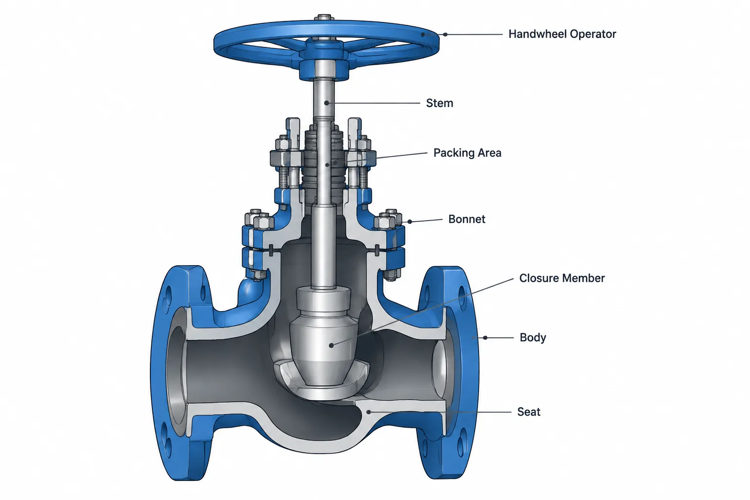
Valve body, bonnet, and trim identify different parts or functional groups within a valve assembly. Keeping these terms separate is essential when preparing valve data sheets, assigning CAD properties, reviewing vendor information, or checking material descriptions.
This guide explains how the terminology relates to the pressure boundary, internal flow-control components, sealing elements, and operating hardware. It also shows why a simplified valve model cannot, by itself, confirm every construction detail or maintenance requirement.
A valve may appear as one component in a piping model, but its description can include several material, construction, and functional categories. Terms such as body, bonnet, trim, seat, stem, and operator do not refer to interchangeable parts of the valve.
Understanding these terms helps designers interpret valve data sheets, build useful CAD properties, review vendor documents, and avoid ambiguous material descriptions. It also prevents a common documentation error: treating the body material as if it describes every pressure-containing, internal, and operating part.
The valve as an assembly
A valve is an assembly installed in a piping system to isolate, regulate, direct, or prevent the reversal of flow. Its exact construction depends on the valve type, end connection, operating method, service, and manufacturer design.
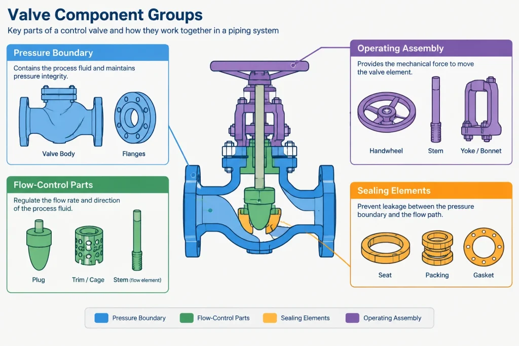
For documentation purposes, it is useful to divide the assembly into functional groups:
- Pressure-boundary parts: parts that contain the process fluid and system pressure.
- Flow-control parts: internal elements that open, close, throttle, or redirect the flow path.
- Sealing parts: seats, packing, gaskets, and related items that limit leakage.
- Operating parts: stems, shafts, handwheels, gear units, actuators, and linkage.
- Fasteners and accessories: bolting, position indicators, limit devices, extensions, drains, vents, and other attachments.
These groups overlap in some designs. A stem, for example, transmits operating force and may also be part of the trim description. The project specification and manufacturer documentation should therefore control the final terminology.
What is the valve body?
The valve body is the principal pressure-containing shell connected to the piping. It includes the main flow passage and normally carries the valve end connections, such as flanged, threaded, socket-weld, butt-weld, or other specified ends.
The body establishes much of the valve’s external geometry. In CAD, it affects face-to-face or end-to-end length, connection locations, outside envelope, nearby pipe clearance, and interference with surrounding equipment or structures.
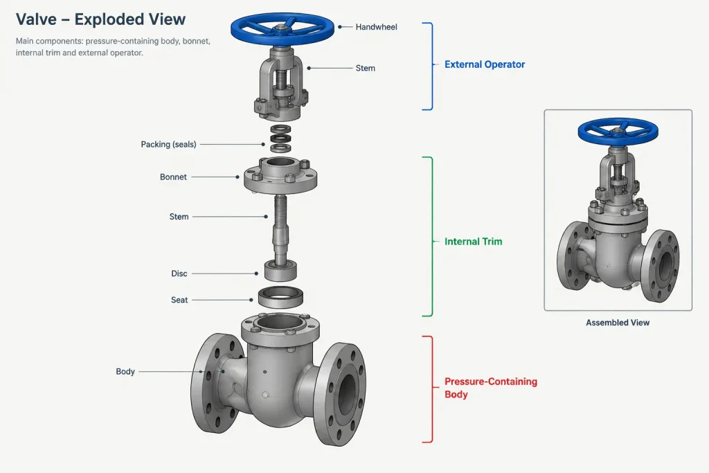
A body material entry describes the material of this principal shell. It should not automatically be applied to the seat, closure element, stem, packing, or operator. Those parts may require different materials because they perform different mechanical, sealing, corrosion, or wear functions.
What is the bonnet?
The bonnet is a pressure-retaining closure attached to the body on many valve designs. It can provide access to internal components and support parts such as the stem, packing, and operating mechanism. Depending on the valve, the corresponding closure may be described by another term, including a cover.
Common construction descriptions distinguish how the bonnet or cover is attached to the body. Designers should preserve the terminology found in the governing valve specification or approved manufacturer data rather than assuming that visually similar closures are equivalent.
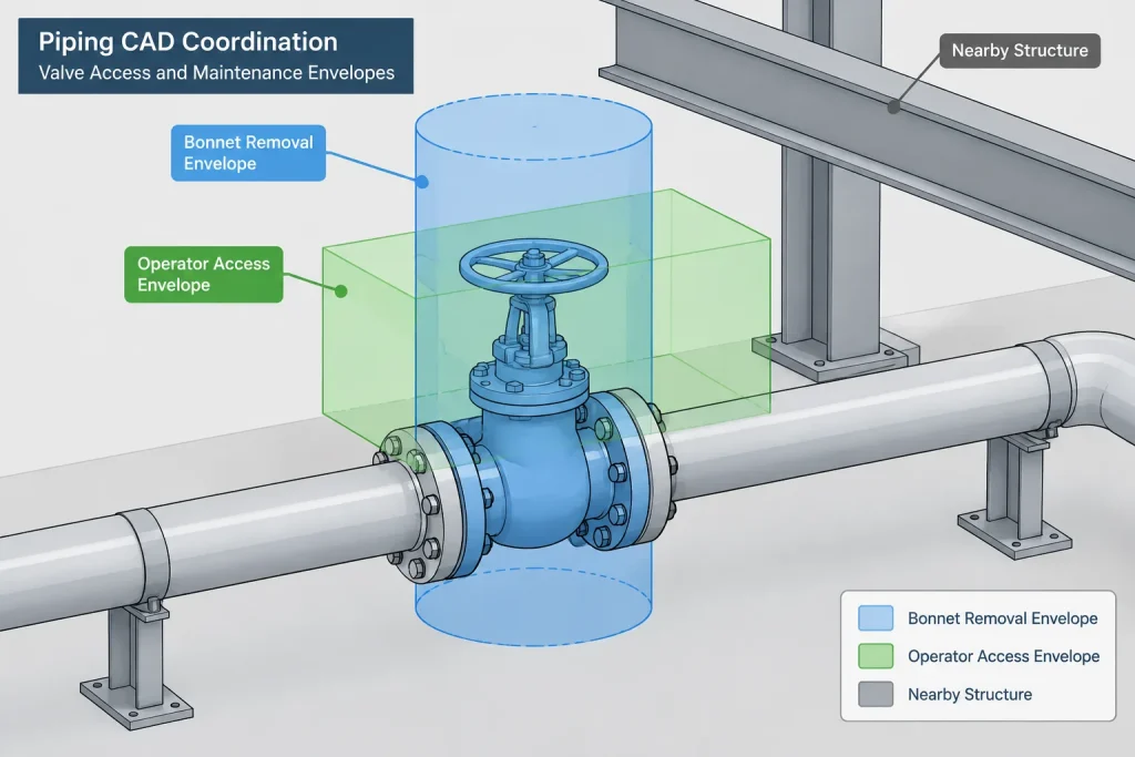
The body-to-bonnet joint is also relevant to layout. A bolted closure may require overhead or side clearance for disassembly and removal of internal parts. A simplified CAD solid that shows only the operating envelope may not reveal this maintenance requirement.
What does valve trim mean?
Valve trim generally refers to selected internal working parts associated with controlling flow, contacting the seat, guiding movement, or transmitting motion. The precise list is not universal across every valve family or specification.
Parts commonly associated with trim descriptions may include:
- The closure member, such as a disc, plug, ball, gate, or needle
- Seat or seat-ring surfaces
- Stem or shaft
- Internal guides, bushings, or related working components
A trim designation is therefore not merely another name for the valve’s internal material. One valve may contain multiple internal materials, coatings, hard-facing treatments, soft sealing elements, and packing materials. A short trim label may summarize only a defined subset of those parts.
When a project uses trim identifiers or standardized trim combinations, the identifier should be interpreted through the applicable project specification and purchasing documents. It should not be decoded from memory or transferred between unrelated valve types without verification.
Seat, closure member, stem, and packing
Seat
The seat is the sealing interface against which the closure member contacts or approaches to limit flow. A valve may use integral body seating surfaces, separate seat rings, replaceable seats, resilient elements, or a combination of constructions.
Seat material can be important to leakage performance, temperature capability, chemical compatibility, wear, and operating torque. The body material alone does not establish these characteristics.
Closure member
The closure member is the moving internal element that changes the flow opening. Its name depends on valve type: a gate in a gate valve, a ball in a ball valve, a disc in several other valve families, or a plug in a plug valve.
The closure member should not be generically called a disc when the valve type uses more specific terminology. Precise naming makes data sheets and review comments easier to interpret.
Stem or shaft
The stem or shaft transfers motion from the operator to the closure member. Linear-motion valves commonly use stem terminology, while rotary valves may use a shaft. Construction details vary, and external stem movement can affect the valve’s operating and maintenance envelope.
Packing and seals
Packing seals around a moving stem where it passes through the pressure boundary. Other seals and gaskets may occur at body joints, covers, seats, or internal interfaces. These sealing materials are not necessarily included in a trim description and should be documented separately when service conditions require control.
Body material, trim material, and soft goods are separate data
| Data category | What it generally describes | Why it matters |
|---|---|---|
| Body and bonnet material | Principal pressure-containing shell parts | Pressure boundary, corrosion compatibility, fabrication, and purchasing |
| Trim description | Defined internal working parts | Wear, seating, corrosion resistance, and operating function |
| Seat construction | Sealing interface and seat components | Shutoff behavior, service compatibility, and replacement |
| Packing and gasket materials | Dynamic and static sealing elements | Leak control and compatibility with process conditions |
| Operator | Manual, geared, powered, or actuated operating assembly | Access, torque delivery, controls, weight, and clearance |
Combining these entries into one general material field can hide important differences. Where the project database permits it, each category should have its own controlled property.
The operator is not normally the trim
The operator is the external mechanism used to position the valve. It may be a lever, handwheel, gear assembly, pneumatic actuator, electric actuator, hydraulic device, or another project-approved arrangement.
Although the operator moves the trim, it is normally documented as a separate assembly. Operator type has significant CAD consequences: it changes the external envelope, access direction, removal space, support loads, control connections, and sometimes the valve’s center of gravity.
A generic valve body with a placeholder handwheel should not be used to confirm actuator clearance. Approved manufacturer geometry or verified envelope information is needed when space is limited.
Recommended CAD and data workflow
A practical valve workflow separates connection geometry from specification data and vendor-dependent details.
- Identify the valve function and type. Confirm whether the valve is intended for isolation, throttling, check service, diversion, or another duty.
- Control the piping interfaces. Record nominal size, end type, facing or preparation, and the verified connection-to-connection dimension.
- Assign the body construction. Use the project piping class, valve specification, or approved purchase description.
- Record trim and sealing data separately. Do not infer them solely from body material or a generic CAD catalog name.
- Model the operator envelope. Include the orientation and clearance needed for operation, removal, and nearby access.
- Replace generic geometry when required. Vendor-dependent valves and actuated assemblies may need verified dimensions before layout is finalized.
- Check deliverable consistency. Compare the model properties, valve list, line specification, data sheet, bill of material, and vendor documents.
Common documentation mistakes
- Describing an entire valve with only the body material
- Assuming every internal component is included in the trim designation
- Using “disc” as the closure-member name for every valve type
- Treating packing, gaskets, and resilient seats as identical data categories
- Leaving the operator type or orientation undefined in a congested layout
- Using generic CAD geometry as evidence of actual bonnet-removal or actuator clearance
- Copying a trim description between different valve types without checking how each specification defines it
A clearer way to describe valves
A useful valve description is layered rather than compressed into one phrase. It identifies the valve type and piping interfaces, then separately controls body construction, internal working parts, sealing materials, and operator requirements.
This approach improves communication between process, piping, materials, procurement, vendors, and maintenance personnel. It also makes the CAD model more useful: geometry controls fit and access, while structured properties preserve the technical distinctions that a simplified solid cannot show.
How to resolve conflicting valve descriptions
Valve information may appear in a piping class, valve list, model property set, purchase description, data sheet, and manufacturer document. If those records use different wording, do not assume that similar terms describe the same components. First determine which document governs the requirement, then reconcile the remaining records against it.
A useful review separates confirmed requirements from vendor-dependent construction. The project may define the valve type, piping connections, body material, trim requirements, sealing requirements, and operator arrangement, while the manufacturer defines the detailed arrangement used to satisfy them. CAD properties should preserve that distinction rather than presenting an assumed internal design as verified.
Geometry and specification data answer different questions
Valve geometry helps a designer evaluate fit, connection points, orientation, operating access, and potential interference. Specification data identifies what the valve must be and how its construction is controlled. Neither is a complete substitute for the other.
- Use model geometry to coordinate the valve with pipe, equipment, structures, access routes, and nearby operating components.
- Use structured properties to record valve type, body construction, trim description, seat or seal information, and operator requirements.
- Use approved manufacturer information when actual external shape, disassembly space, moving-part travel, or actuator configuration affects the layout.
- Use project documents to resolve terminology and determine which material or construction fields must be controlled separately.
Practical quality checks for valve records
Before issuing a model or valve schedule, check whether each material description clearly identifies the part or group to which it applies. A bare material entry can be misleading when the field name does not distinguish the body, bonnet, closure member, seat, stem, packing, or gasket.
Also verify that the modeled operator matches the documented operating method and orientation. Where the geometry remains generic, identify it as preliminary or representative according to the project workflow. This prevents users from treating an uncluttered CAD shape as proof of actual access or maintenance clearance.
Frequently asked questions
Is valve trim the same as every part inside the valve?
No. Trim generally covers a defined selection of internal working parts, but its exact scope can vary with the valve family, specification, and purchasing description. Seals, packing, gaskets, and other internal items may be documented separately.
Does the body material also define the bonnet material?
Not automatically. Some descriptions group body and bonnet construction, while others control them separately. Use the governing project specification and approved valve documentation rather than extending a body entry to another component by assumption.
Is the seat always part of the trim?
The seat or seat-ring surfaces are commonly associated with trim, but terminology is not universal. Confirm how the applicable project or manufacturer document defines the trim designation.
Should an actuator be entered as trim?
Normally, the actuator or other operator is documented as a separate external assembly. It affects operation, controls, access, support considerations, and the valve envelope even though it moves the internal flow-control components.
Can a generic CAD valve confirm maintenance clearance?
No. Generic geometry can support preliminary arrangement work, but it may omit bonnet removal, stem movement, actuator travel, fastener access, and disassembly space. Use verified envelope and maintenance information before finalizing a constrained layout.
What should be checked when valve records disagree?
Identify the governing document, compare component-specific fields, and resolve differences with the responsible project discipline or approved manufacturer information. Do not combine conflicting descriptions into a single generalized material field.