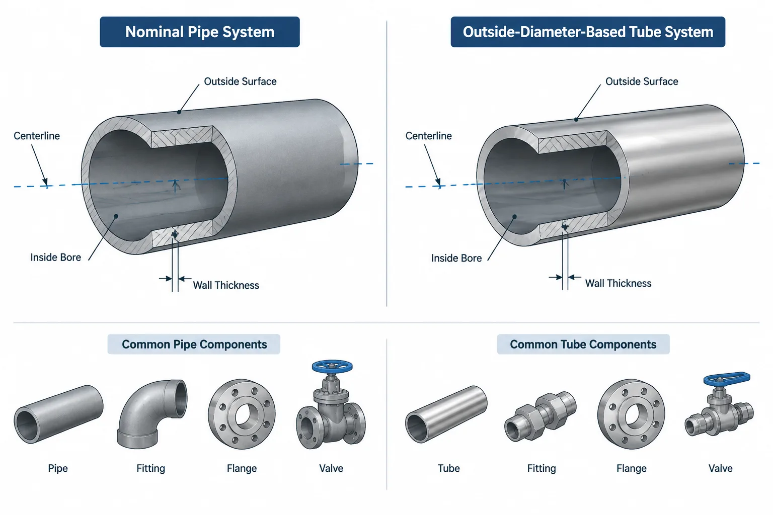
Pipe vs. tube in piping CAD is a data-control issue as much as a geometry issue. A correct model must preserve the product type, sizing convention, wall definition, connection family, and specification boundary behind each cylindrical component.
This guide explains how to distinguish pipe and tube during component selection, modeling, annotation, material reporting, and interface review. It also shows why visual alignment alone cannot establish that parts are compatible.
Pipe and tube can look nearly identical in a CAD model: both may appear as hollow cylinders following a centerline. In engineering documentation, however, the terms describe different product conventions. The distinction affects size callouts, wall selection, fittings, end connections, material takeoffs, and the data assigned to a modeled component.
The practical difference is not simply that pipe is large and tube is small. Either product can be available across a range of sizes. The more useful distinction is how the product is specified and which compatible component system surrounds it.
The basic distinction between pipe and tube
Pipe is commonly identified by a nominal pipe size, such as NPS in United States practice or a related DN designation in metric documentation. A nominal size is a standardized name rather than a direct measurement of either the outside diameter or the inside diameter. Pipe wall is then identified separately, often by a schedule or another applicable wall designation.
Tube is commonly specified by an outside diameter and a wall thickness. That description makes the physical geometry more explicit, although users must still confirm whether the stated values are nominal, minimum, or subject to manufacturing tolerances. Some tubing product systems use other conventions, so the governing product specification and supplier data remain important.
| Topic | Pipe | Tube |
|---|---|---|
| Primary size language | Usually a nominal pipe size or corresponding DN designation | Often outside diameter plus wall thickness |
| Wall identification | Frequently schedule or another pipe wall designation | Frequently stated wall thickness; other conventions may also be used |
| Compatible components | Pipe fittings, flanges, valves, and branch components made for the applicable piping system | Tube fittings, compression fittings, sanitary fittings, or other system-specific components |
| CAD classification | Pipe component with nominal size, wall data, and piping specification | Tube component with explicit dimensional and connection data |
| Interchangeability | Must be verified; a similar appearance or size label does not establish compatibility | |
Why a size label is not enough
A pipe designation cannot safely be compared with a tube designation by reading only the nominal label. The pipe outside diameter comes from its dimensional system, while the tube outside diameter may be stated directly. Even when the two values appear close, the products may have different tolerances, wall conventions, material requirements, and available connections.
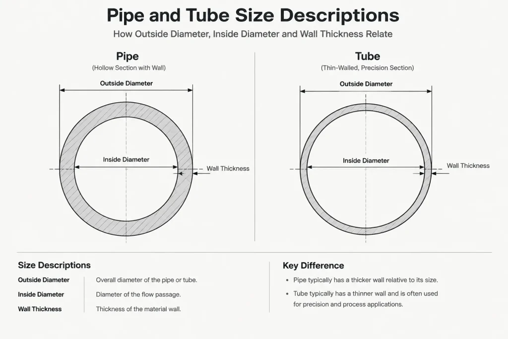
Inside diameter is also not a reliable basis for substitution. For pipe, changing the wall designation generally changes the bore while the standardized outside diameter for that nominal size remains associated with the pipe series. For tube, the bore is normally derived from the specified outside diameter and wall thickness. In either case, actual manufactured geometry can vary within the applicable tolerance.
A CAD designer should therefore avoid mapping a tube to a pipe merely because their bores or outside envelopes look similar. Compatibility must be established through the complete component definition.
Connection systems often reveal the real difference
The surrounding connection system is frequently more important than the straight product itself. Pipe may connect through butt-weld, socket-weld, threaded, flanged, grooved, or other piping joints. Tube may use compression-type fittings, welded tube fittings, mechanical connectors, sanitary connections, or a process-specific joining system.
A component described as suitable for a particular tube outside diameter is not automatically suitable for a pipe carrying a similar nominal size. A compression fitting, for example, depends on controlled contact with the tube outside surface. A pipe fitting may instead depend on standardized socket geometry, thread form, weld preparation, flange dimensions, or another interface.
Connection review should include:
- the actual outside diameter accepted by the fitting;
- the permitted wall range or bore condition;
- the end-preparation or surface requirements;
- the material and product specification;
- the joint method and required assembly space;
- the applicable pressure-temperature and service requirements;
- the dimensional source used for the CAD component.
How pipe and tube should be represented in CAD
Keep the component classes separate
A tube should not be created by scaling a pipe component, and a pipe should not be renamed as tube without changing its dimensional and specification data. Separate component classes make it easier to control connection rules, nominal descriptions, wall properties, bills of material, and drawing annotations.
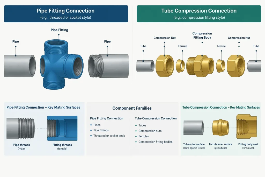
Even if the graphical solids are identical, the metadata may need to be different. A pipe object might carry NPS, DN, schedule, line number, and piping class fields. A tube object might instead carry outside diameter, wall thickness, tube specification, fitting series, and system-specific connection information.
Model the geometry required for the task
For general arrangement work, centerlines and outside envelopes may be sufficient. Detailed fabrication or connection design may require the bore, fitting insertion, weld location, ferrule position, clamp envelope, or other interface geometry. The model level of detail should match the intended deliverable rather than attempting to show every manufacturing feature everywhere.
When wall thickness affects flow calculations, weight, weld preparation, or fabrication, it should be retained as controlled data even if the model displays only the outer envelope.
Use connection validation instead of visual snapping
Two cylindrical parts can be coaxial and still be incompatible. CAD connection logic should check more than centerline alignment. Depending on the system, useful validation fields include component type, outside diameter, nominal size, end connection, facing or fitting series, wall range, material class, and specification boundary.
A visually clean joint should not be treated as proof that the real components connect.
Handling a pipe-to-tube transition
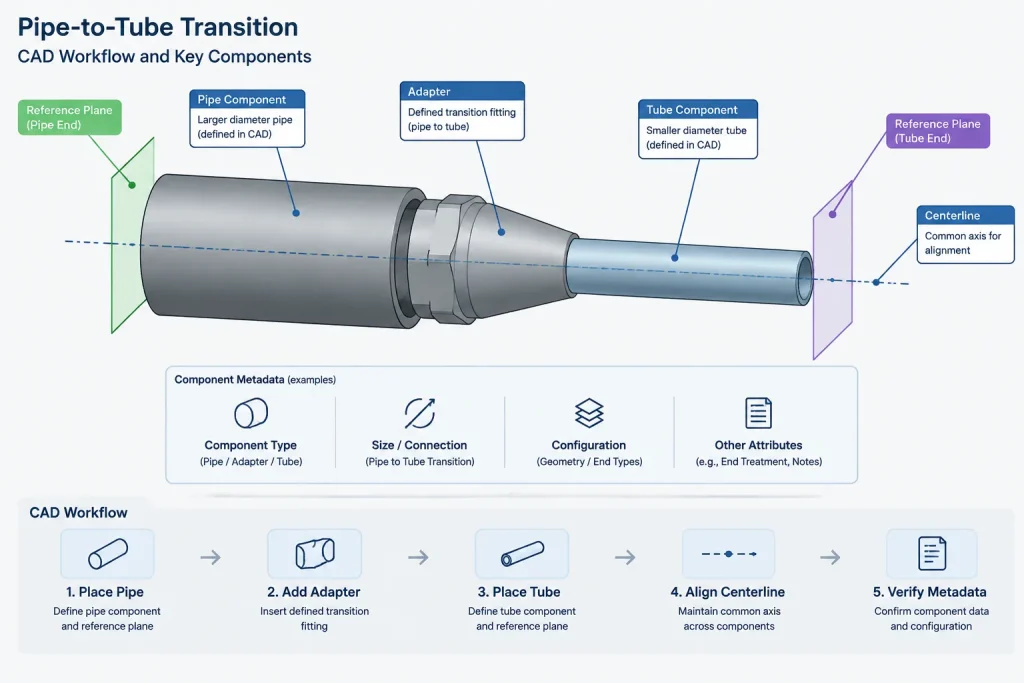
A change from pipe to tube should be modeled and documented as an intentional interface. The transition may be a listed adapter, a fitting assembly, a welded detail, an equipment connection, or a project-specific design. The correct solution depends on the service, materials, pressure-temperature basis, joining method, and governing documents.
In the CAD model, identify reference planes on both sides of the transition. One side may connect using pipe nominal size and schedule data, while the other uses tube outside diameter and wall data. The transition component should carry the dimensional source for each end rather than inheriting one size convention across the entire object.
The transition also creates a possible specification break. Drawings and material reports should make clear where the pipe system ends, where the tube system begins, and which document controls the adapter. If the interface is supplied with equipment or an instrument package, ownership and model boundaries should also be recorded.
Common drafting and modeling errors
- Assuming equal nominal labels mean equal outside diameters: nominal terminology belongs to a specific product system.
- Using bore alone to select a transition: the outside geometry, wall, fitting interface, and joint method may control compatibility.
- Calling every hollow round product pipe: this can produce incorrect material descriptions and fitting selections.
- Scaling a library part: scaling may alter geometry without creating a valid manufactured size or connection.
- Omitting wall data from tube objects: the outside envelope may remain correct while the bore, weight, and connection suitability become wrong.
- Mixing structural tubing with process tubing: similar geometric descriptions do not mean the products serve the same engineering function.
- Hiding the transition in a generic connector: this can prevent procurement and fabrication teams from identifying the required adapter.
A practical CAD verification workflow
- Identify whether each straight product is pipe, process tube, instrumentation tube, sanitary tube, structural tubing, or another defined product.
- Confirm the sizing convention used on each side: nominal size, outside diameter, wall thickness, schedule, or another controlled designation.
- Verify the dimensional source and applicable product specification.
- Check the actual connection type and fitting compatibility rather than relying on centerline alignment.
- Represent every pipe-to-tube interface with a defined transition component or approved project detail.
- Assign metadata that supports drawings, material takeoffs, line lists, and procurement descriptions.
- Review the model against current manufacturer information when the component geometry is not fully standardized or is product-specific.
The key documentation principle
Pipe and tube are not interchangeable labels for the same geometry. Pipe is usually organized around a nominal sizing system and associated wall designations. Tube is often identified more directly by outside diameter and wall thickness, but its exact convention must still be verified.
In CAD, the safest approach is to preserve that distinction in both geometry and data. Model the correct outside envelope, retain the wall information needed by the project, use the proper fitting family, and document every transition explicitly. This prevents a cylinder that looks correct on screen from becoming an incompatible component in fabrication or procurement.
Model handoff and quality-control considerations
The pipe-or-tube classification should remain consistent as information moves from the specification or supplier record into the component library, model, drawing, and material report. If one deliverable describes a component as pipe while another treats it as tube, connection requirements and purchasing descriptions can become ambiguous even when the displayed geometry is unchanged.
Check the source behind each component
A useful model review asks where the component dimensions and connection rules came from. Generic geometry may be acceptable for early layout work, but procurement or fabrication documentation requires controlled component definitions. Product-specific interfaces should be checked against the applicable project documents and current manufacturer information.
Protect classification during model changes
Replacing a component, changing wall data, or crossing a specification boundary should trigger more than a graphical update. Review the component description, end conditions, fitting family, material assignment, reporting fields, and connected parts. A replacement that occupies the same model envelope may still represent a different product system.
Make review status visible
When an interface has not been fully resolved, identify it as requiring verification rather than disguising it with a generic connector. This helps engineering, drafting, procurement, and fabrication teams distinguish approved transitions from temporary layout assumptions.
Questions for a CAD model review
- Is each straight component classified as the correct product type?
- Does its size callout follow the sizing convention used by that product?
- Is wall information stored in a controlled field rather than implied by appearance?
- Do connected fittings accept the actual product geometry and end condition?
- Are pipe-to-tube transitions represented as identifiable components or approved details?
- Do drawings and material reports preserve the same terminology used in the model?
- Are unresolved or manufacturer-specific interfaces clearly marked for verification?
Pipe vs. tube in piping CAD FAQs
Can pipe and tube have the same CAD appearance?
Yes. Both can appear as hollow cylinders or simplified outside envelopes. Their visual similarity does not establish equivalent dimensions, wall conventions, tolerances, specifications, or connection compatibility.
Is tube always specified by outside diameter and wall thickness?
Tube is often described that way, but the convention must be confirmed from the governing product specification and supplier information. Some tube systems use additional or different designations.
Can a tube component be made by scaling a pipe model?
No valid component definition is created by scaling alone. Scaling changes geometry without confirming an available product size, fitting interface, wall definition, material description, or connection rule.
Why should wall data be retained when only the outside envelope is modeled?
Wall information can affect the bore, component description, weight-related data, fabrication requirements, and connection suitability. It may therefore remain essential even when the visible model is simplified.
How should a pipe-to-tube connection appear in a model?
It should be represented as an intentional interface using a defined adapter, fitting assembly, equipment connection, approved detail, or other controlled transition. The model and related documents should show where each product system begins and ends.
Does centerline alignment prove that two components connect?
No. Coaxial components may still have incompatible outside dimensions, end preparations, fitting systems, wall conditions, materials, or specification requirements. Connection data must be reviewed independently of visual alignment.