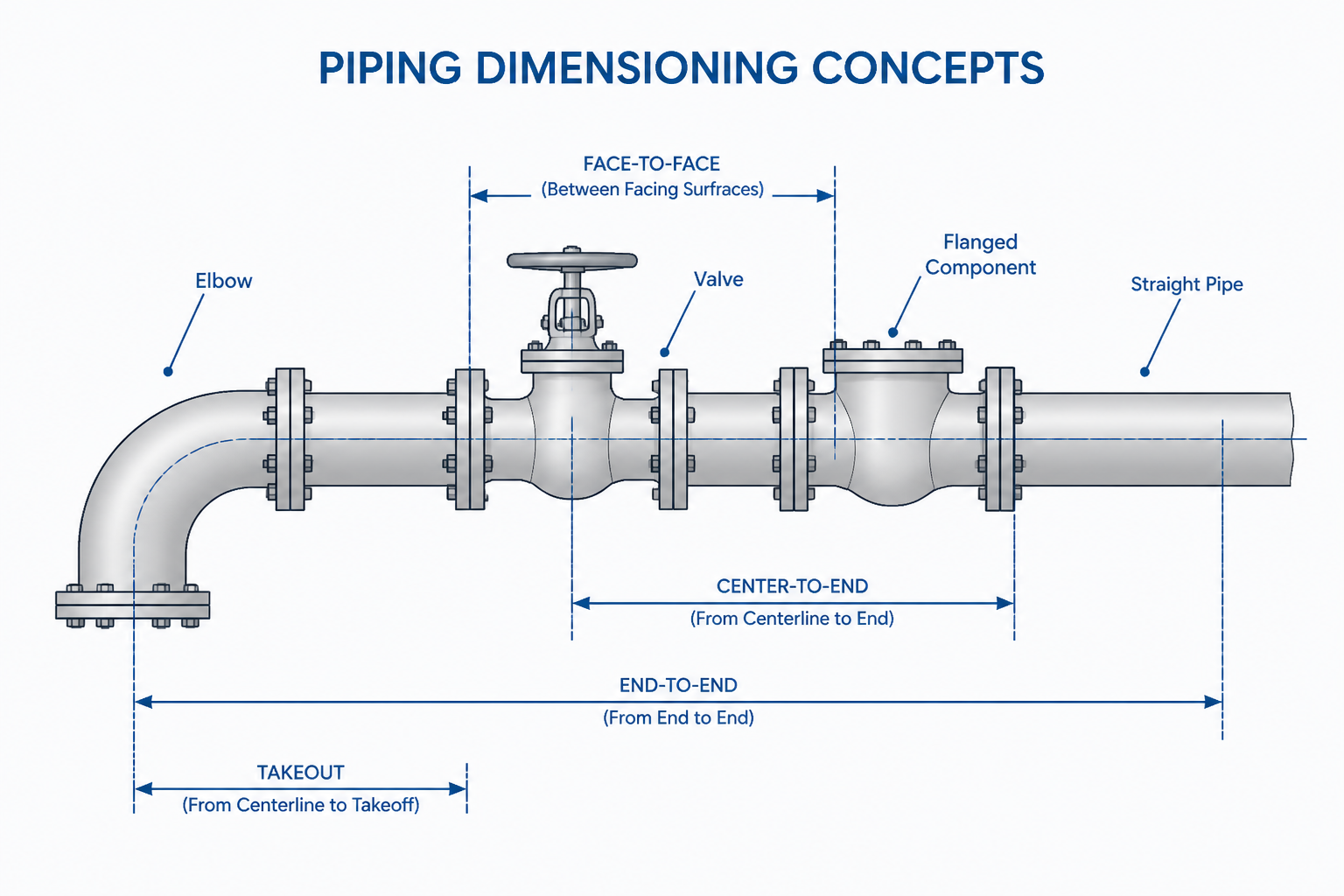
Accurate piping CAD depends on more than selecting a component that looks correct on screen. The dimensional convention behind each fitting, valve, flange, or specialty item determines how its connection points align with the surrounding route.
This guide explains how to distinguish face-to-face, center-to-end, end-to-end, and takeout dimensions, then apply the correct reference points when building models, plans, isometrics, and spool drawings.
Piping component dimensions in CAD determine where a fitting, valve, flange, or specialty item actually ends up in the model and on the finished drawing. A component may look correct in a block library while still producing an incorrect route if the wrong dimensional convention is used.
The most common sources of confusion are face-to-face, center-to-end, end-to-end, and takeout dimensions. These terms describe different ways of locating the connection points of a component. Understanding the difference helps drafters build accurate centerlines, avoid accumulated errors, and check whether a reference table is being applied correctly.
Why component dimensions matter in piping CAD
Most piping layouts are developed from connection points and centerlines rather than from the visible outside shape of a component. The software or drafter must know where the pipe terminates, where the fitting changes direction, and where a flange or valve occupies space.
If a component is inserted using an incorrect length, several downstream problems can appear:
- Adjacent pipe segments become too short or too long.
- Flange faces no longer align with equipment or another spool.
- Dimensions on plans and isometrics disagree.
- Weld locations shift from the intended fabrication arrangement.
- Clearance checks are based on the wrong physical envelope.
- Material takeoffs and spool break locations may require rework.
The key principle is simple: use the dimension that matches the component’s connection geometry, not merely the dimension that is easiest to find in a catalog or block description.
Face-to-face dimensions
A face-to-face dimension measures the distance between two defined end faces. It is commonly associated with components that have a recognizable inlet and outlet face, such as certain valves, strainers, specialty items, and flanged assemblies.
In CAD, the face-to-face value is useful when both connection faces are perpendicular to the component centerline and the drawing or model is intended to show the physical installed length between those faces. The value does not necessarily represent the length of the visible body. Bonnet shapes, handles, bolting, and other projections may extend beyond the face-to-face envelope.
When using this dimension, confirm:
- Which faces are included in the measurement.
- Whether the value applies to a bare component or an assembled item.
- Whether gaskets, spacers, adapters, or mating flanges are excluded.
- Whether the CAD block insertion points are located on the same faces.
Center-to-end dimensions
A center-to-end dimension locates a connection end from a theoretical centerline intersection or bend center. It is especially important for elbows and other fittings that change direction.
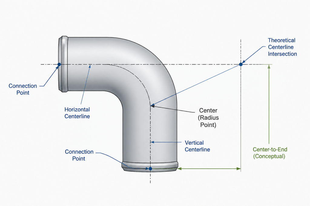
For an elbow, the centerline intersection is usually not a physical point on the fitting. It is a geometric construction point used to define the route. The center-to-end value allows the drafter to place the elbow between two pipe centerlines without relying on the outside silhouette.
In a CAD workflow, the fitting block should normally use connection points that correspond to the ends of the fitting centerline. If the block is drawn from the outer profile instead, the route can appear visually plausible but produce incorrect pipe lengths and bend locations.
Center-to-end checks for directional fittings
When checking an elbow or similar fitting, verify that:
- The two connection points lie on the intended pipe centerlines.
- The bend direction matches the route and orientation of the fitting.
- The insertion point is defined consistently across the component library.
- The dimension is not being confused with outside radius or tangent length.
End-to-end and end-to-center dimensions
End-to-end describes the distance between two connection ends. It may be used for a straight component, a reducer, or a fitting whose two ends are measured directly. End-to-center describes the distance from one connection end to a theoretical centerline location, such as the center of a branch or the center of a symmetrical fitting.
These terms can look similar in a reference table, but they support different CAD operations. An end-to-end dimension can define the total length of a straight segment. An end-to-center dimension may be needed to position a branch connection or align the component with another route.
| Dimension type | What it locates | Typical CAD use |
|---|---|---|
| Face-to-face | Two component faces | Positioning valves, strainers, or flanged items |
| Center-to-end | A theoretical centerline point to a connection end | Placing elbows and directional fittings |
| End-to-end | Two connection ends | Defining the installed length of a straight or reducing component |
| End-to-center | A connection end to a centerline or branch center | Aligning branches and symmetrical fittings |
| Takeout | The portion used by a fitting or component in a layout calculation | Calculating remaining pipe length between connection points |
What “takeout” means in a piping layout
Takeout is a layout term rather than one universal physical measurement. It generally describes the amount of a route occupied by a fitting or component when determining the remaining straight pipe length.
For example, when a pipe run contains a fitting between two known locations, the drafter must subtract the applicable fitting contribution from the overall route. The correct subtraction depends on how the fitting is defined and how the drawing’s dimensions are established. A takeout may be based on a center-to-end value, an end-to-center value, or another project-defined convention.
Do not assume that takeout is interchangeable with face-to-face length. Two components can occupy a similar region in a drawing while requiring different centerline calculations. Always identify the reference points used by the table, block, or design software.
A practical CAD workflow
1. Identify the connection geometry
Before inserting the component, determine whether the item connects by butt weld, flange, threaded end, socket connection, or another end condition. The connection type affects where the usable endpoint is located.
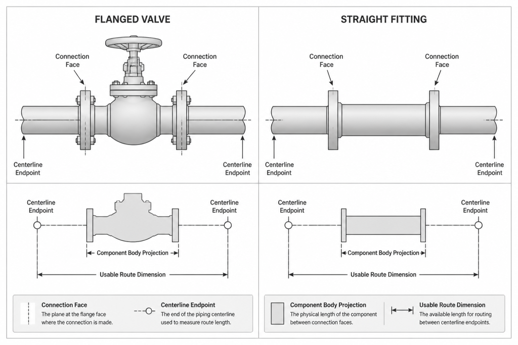
2. Select the correct dimensional convention
Read the table heading, sketch, or component description carefully. Look for terms such as face-to-face, center-to-end, end-to-end, or takeout. Do not infer the meaning from a single unlabeled value.
3. Match the block insertion points
Set the block or parametric component’s connection points at the locations used by the dimension source. For an elbow, these are normally the ends of the fitting centerline. For a flanged item, they may be the mating faces or the pipe-side connection points, depending on the project convention.
4. Route from connection point to connection point
Build the adjacent pipe segments from the component endpoints rather than from the visible edge of the symbol. This keeps the centerline route independent of lineweight, hatch, body shape, and annotation graphics.
5. Check the dimensional chain
Review the full route from a known reference point. Confirm that each component contribution is counted once and that no gasket, flange, weld, or spool allowance has been added or omitted unintentionally.
6. Review the physical envelope separately
Connection dimensions locate the route, but they do not describe every projection. Check handwheels, actuators, bonnets, bolting, removable covers, insulation, and maintenance access as separate clearance items.
Common drafting mistakes
- Using outside-body length as pipe length: the visible outline may not coincide with the connection centerline.
- Mixing face dimensions and centerline dimensions: this creates a systematic offset at fittings and valves.
- Mirroring without checking connection points: a mirrored block can reverse a branch, actuator, or orientation attribute.
- Relying on an unverified generic block: similar-looking components may use different dimensional conventions.
- Ignoring the source table’s scope: dimensions can depend on component type, end preparation, rating category, or project specification.
- Dimensioning the drawing graphic instead of the route: annotations should reference meaningful design points.
Final review checklist
Before issuing a plan, elevation, isometric, or spool drawing, verify that every component has a clear dimensional basis. Confirm the source value, the connection-point definition, the block orientation, and the resulting pipe lengths. Then compare the CAD geometry with the applicable component reference page and project material requirements.
Accurate piping component dimensions in CAD are less about memorizing terminology than about maintaining a consistent chain of reference points. Once face-to-face, center-to-end, end-to-end, and takeout dimensions are treated as distinct tools, routing becomes easier to check and much less vulnerable to hidden accumulated errors.
How to use this reference when checking a CAD model
Use the terminology as a map between the dimensional source and the geometry in the drawing. First identify the connection points used by the component reference. Then confirm that the CAD block, parametric family, or library object places those points in the same locations.
This distinction is especially important when a component has a large visible body, an actuator, bolting, or another projection beyond its connection geometry. The route should be controlled by the defined connection points, while the surrounding physical envelope should be reviewed separately for clearance, access, insulation, and maintenance considerations.
A useful review sequence
- Read the dimensional heading and any accompanying sketch before selecting a value.
- Identify whether the reference is based on faces, ends, centerlines, or a project-defined takeout.
- Check that the CAD insertion point and connection points use the same convention.
- Compare the resulting centerline route with adjacent components and known reference locations.
- Review body projections and access requirements separately from the route dimension.
This approach helps prevent a common drafting error: treating a visual match as proof that the component is geometrically correct. A reliable piping model must agree with both the dimensional reference and the intended connection geometry.
Why dimensional consistency matters across deliverables
The same component may appear in a plan, elevation, isometric, spool drawing, material takeoff, or fabrication package. If its insertion points are based on different conventions in different views, the discrepancy can propagate into pipe lengths, weld locations, flange alignment, and field coordination.
Maintaining one clearly documented dimensional basis makes the component library easier to audit and reduces rework when drawings are revised. It also gives reviewers a practical way to trace an apparent discrepancy back to the source value, the block definition, or the route calculation.
Frequently Asked Questions
Is face-to-face the same as takeout?
No. Face-to-face identifies the distance between defined component faces, while takeout describes the portion of a route occupied by a fitting or component for layout calculations. A project may define takeout using a different reference convention.
Why are center-to-end dimensions important for elbows?
An elbow changes direction around a theoretical centerline intersection. Center-to-end dimensions allow the drafter to position the elbow between pipe centerlines without using the outside shape of the fitting.
Should CAD blocks be drawn from the outside profile?
The outside profile can be useful for showing the physical envelope, but connection points should be placed according to the dimensional reference used for routing. A visually accurate outline does not guarantee accurate pipe geometry.
What should be checked before using a takeout value?
Confirm the reference points, component type, connection condition, and project convention. Also check whether related items such as flanges, gaskets, adapters, welds, or spool allowances are included or excluded.
Do connection dimensions show the full clearance envelope?
No. Connection dimensions locate the route between defined endpoints. Handles, actuators, bonnets, bolting, removable covers, insulation, and maintenance space must be reviewed as separate physical and access considerations.
How can a drafter find the source of a route mismatch?
Trace the dimensional chain from a known reference point and compare each component contribution with the source table or sketch. Then verify the block insertion point, orientation, connection type, and whether any contribution has been counted twice or omitted.