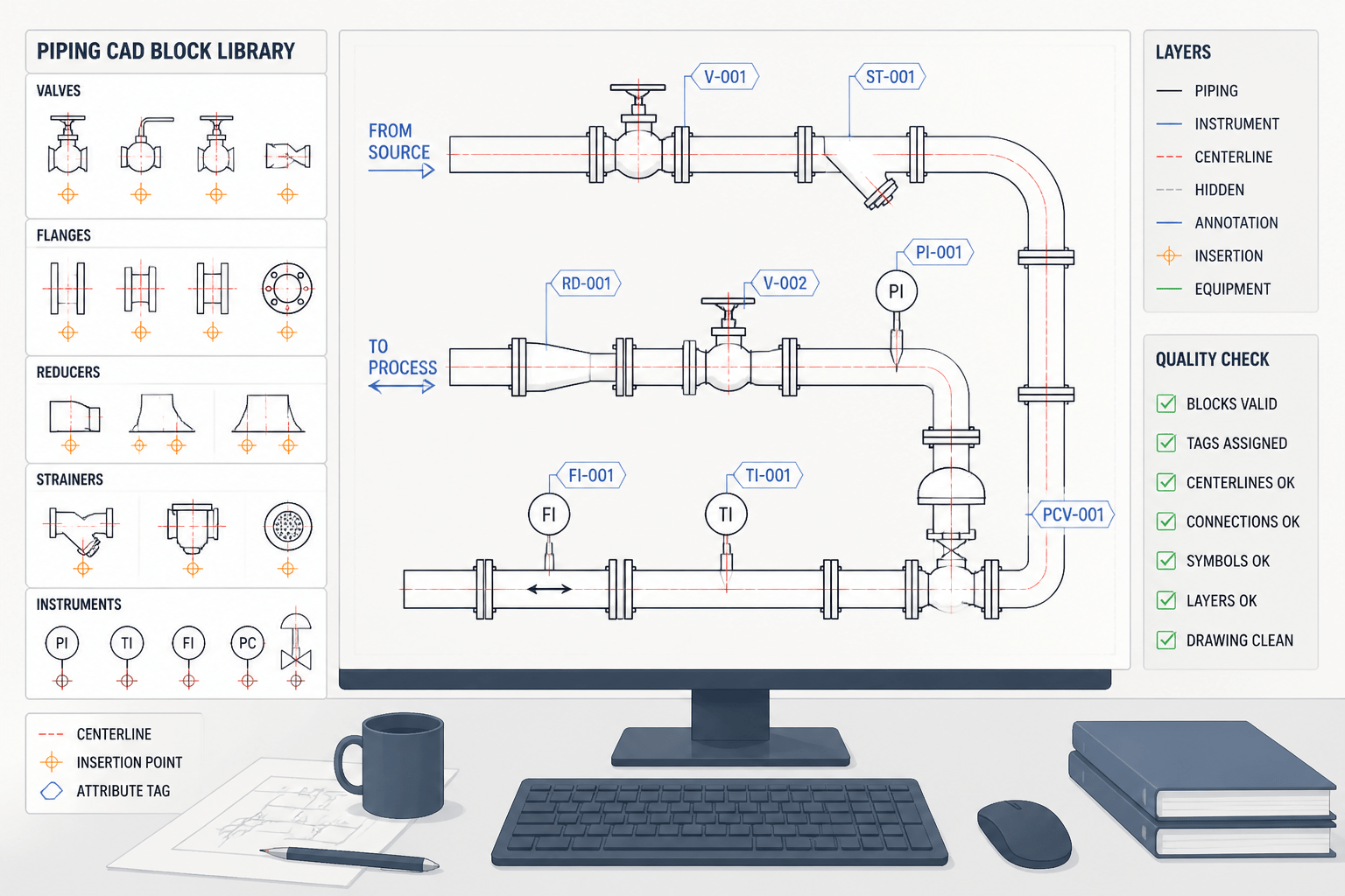
Reliable piping CAD blocks do more than speed up drafting. They help a team place components consistently, preserve connection intent, and separate graphic representation from the dimensional and specification data that controls the real item.
This guide is useful for CAD managers, piping designers, and drafters developing a shared component library. Use it alongside the site’s pipe dimensions and schedules, fitting terminology, flange references, and CAD/DWG resources when checking whether a block represents the intended component and drawing purpose.
Piping CAD blocks can save substantial drafting time, but only when they preserve the information a drawing actually needs. A block that looks correct on screen may still have the wrong insertion point, missing connection data, unsuitable annotation, or an unreliable representation of the component.
This guide explains a practical workflow for building and using a piping CAD block library. It focuses on drafting control and design intent rather than on any one manufacturer’s catalog or a particular project standard. Always verify component dimensions, pressure class, material, facing, and end connection against the project’s approved reference data before issuing a drawing.
What makes a piping CAD block useful?
A piping block is more than a collection of lines and arcs. It is a reusable graphic representation of an item such as a valve, flange, strainer, reducer, instrument connection, or specialty fitting. A useful block should communicate the component clearly while remaining easy to place, edit, review, and extract into downstream documentation.
Before creating a block, decide what level of information it must represent. A plan-view layout block may need only the component outline and connection points. A fabrication detail may require additional geometry, orientation marks, item identification, and notes. Using one overly detailed block for every purpose can make drawings slow and difficult to read.
- Graphic clarity: The shape should be recognizable at the drawing scale where it will be used.
- Connection logic: End points should correspond to the intended pipe centerline or connection location.
- Insertion control: The block should have a predictable base point and orientation.
- Data consistency: Attributes should use stable names and a defined format.
- Layer behavior: Lines, centerlines, text, and reference geometry should behave consistently with the drawing template.
Separate geometry from component data
One of the most common library problems is mixing visible geometry with information that belongs in schedules, tags, or specifications. For example, a valve block may show a general valve symbol, while the line list or piping material specification controls the actual valve type, rating, trim, and body material.
Use the block to show what the reader needs to understand the arrangement. Store project-controlled information in attributes or linked data only when the CAD workflow supports it reliably. Avoid embedding unverified dimensions or performance information in a generic block. The block should not become an unofficial replacement for the project specification or an authoritative pipe and fitting reference table.
| Block element | Typical purpose | Common control question |
|---|---|---|
| Visible outline | Shows the component’s drafting representation | Is it legible at the intended scale? |
| Connection points | Defines where pipe geometry meets the component | Do they align with the pipe centerline? |
| Insertion point | Controls placement and rotation | Can a drafter place it without extra cleanup? |
| Attributes | Stores tag, service, item, or description data | Are field names and formats consistent? |
| Reference geometry | Supports alignment or coordination | Will it plot or remain non-printing as intended? |
Choose the right insertion point
The insertion point determines how efficiently a block can be placed and moved. For inline piping components, a logical base point is usually located on the pipe centerline at a connection or at a meaningful center of the component. For equipment nozzles, a connection point may be more useful than the geometric center of the outline.
Choose a base point that matches the drafting action. If users normally place the block onto an existing pipe run, the insertion point should make that operation direct. If the component is positioned from a nozzle or support reference, use that relationship instead. The best point is not always the visual center.
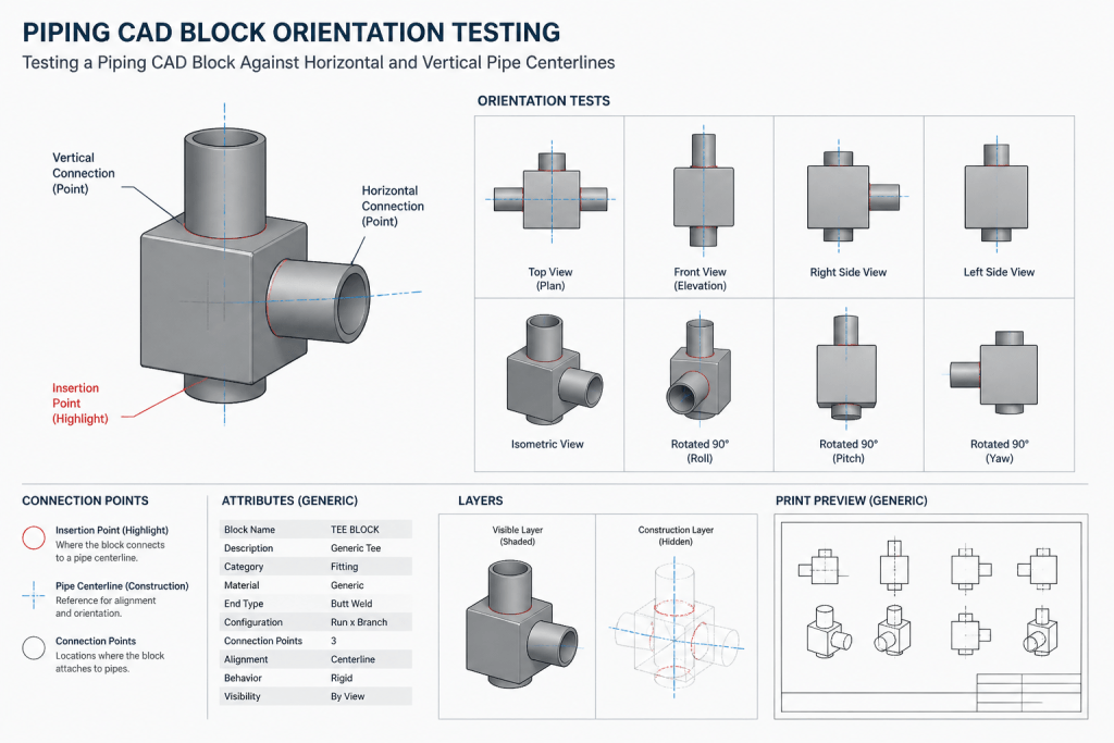
Test the block in its most common orientations. Rotate it, mirror it when appropriate, and place it against horizontal and vertical pipe runs. Check whether the tag remains readable and whether the connection points stay on the expected axis. A block that works in one orientation but requires manual stretching in another will create inconsistent drawings.
Use attributes deliberately
Attributes can make a piping CAD block valuable for drawing coordination, but excessive or inconsistent fields reduce their usefulness. Start with the information that the project actually needs to display or extract. Depending on the drawing type, this may include an item number, valve tag, line reference, service identifier, or short description.
Define attribute names before creating a large library. For example, decide whether the project uses TAG, ITEM, and DESCRIPTION, or a different controlled naming convention. Keep the field names stable even if the displayed prompts change. Consistent names support selection, editing, quality checks, and schedule extraction.
- Use short, predictable attribute names.
- Set a clear text height and justification for each drawing environment.
- Decide whether attributes rotate with the block or remain readable on the sheet.
- Keep optional fields from creating blank, visually distracting labels.
- Do not place project-specific data in a generic library block unless the workflow clearly identifies it as an example or template value.
Control layers, colors, and plotting
A block can carry its own layer structure, inherit the current layer, or use a combination of both. The correct choice depends on the CAD standard and the intended use. A reusable library should not unexpectedly introduce layers that conflict with the project template.
Review how the block behaves in model space and in plotted output. Centerlines may need a different linetype from visible outlines. Construction geometry may need to remain non-printing. Text should follow the drawing’s annotation system rather than using a hard-coded appearance that becomes unreadable in another view.
Where possible, keep block geometry on controlled layers and use properties that allow the project template to manage color and lineweight. Avoid relying on screen color alone to communicate component meaning. Printed drawings, monochrome exports, and PDF markups may not preserve that distinction.
Build separate representations for separate purposes
A single component may need more than one block representation. A plan layout, piping isometric, fabrication detail, and equipment arrangement do not necessarily require the same graphic content. Instead of adding every possible feature to one complex block, maintain purpose-specific versions with clear names.
For example, a layout block may emphasize centerline placement and overall envelope, while an isometric symbol may emphasize the valve body and orientation. A detail block may show additional connection or bolting information. The exact content should follow the project drafting practice and the level of detail required by the deliverable.
Name blocks so users can understand their purpose without opening them. Include useful descriptors such as view type, component family, or annotation behavior. Avoid names that depend only on an internal file number or a drafter’s initials.
Quality-check a block before adding it to the library
Library review should be a repeatable check, not an informal visual glance. Insert the block into a clean test drawing and verify its geometry, data, and behavior.
- Confirm the insertion point and connection points.
- Rotate the block through the orientations used in the project.
- Check layer assignment, color, linetype, lineweight, and plotting.
- Edit every attribute and confirm that text remains readable.
- Test placement against pipe centerlines and nearby components.
- Verify that the block does not contain stray geometry, duplicate lines, or obsolete notes.
- Open the block for editing and confirm that its internal structure is understandable.
- Record the block name, intended use, revision status, and source of any controlled component data.
When a block represents a dimension-dependent component, compare its geometry with the approved project data before release. Do not assume that a visually similar symbol represents the same face-to-face length, connection type, pressure class, or manufacturer configuration. Those details belong to the applicable reference pages, project specifications, and approved vendor information.
Organize the library for real drafting work
Separate general-purpose blocks from project-specific content. A practical library structure might group items by component family, drawing view, and annotation behavior. Include a simple index or preview sheet so users can identify the correct block without inserting multiple candidates into a live drawing.
Establish ownership for updates. When a component representation changes, users should be able to tell which version is current and whether existing drawings need review. Keep obsolete blocks available only when necessary for legacy drawings, and label them clearly so they are not selected for new work.
For related research, connect the library workflow with your site’s pipe dimensions and schedule references, fitting terminology guides, and flange reference pages. These resources help drafters distinguish between a graphic symbol and the dimensional or specification data that controls the real component.
Final drafting principle
A reliable piping CAD block is predictable, limited to its intended purpose, and easy to verify. The goal is not to create the most detailed symbol possible. The goal is to make the correct component easier to place, identify, coordinate, and review without hiding important design decisions inside an uncontrolled drawing object.
How to use this workflow with reference data
A CAD block should communicate arrangement and drafting intent, but it should not be treated as the authority for component dimensions, pressure class, material, facing, or end connection. Those details should be checked against the applicable project specification, approved vendor information, and controlled engineering references.
For example, consult the site’s pipe dimensions and schedule references when a block must align with a pipe centerline or related dimensional data. Use the fitting terminology guides to confirm that a component family is being named and represented consistently, and review the flange reference pages when flange-facing or connection information affects the drawing. The site’s CAD/DWG reference resources can provide a related starting point for file organization and drafting reuse.
A practical review sequence is to identify the drawing purpose, confirm the required connection and annotation behavior, test the block in a clean drawing, and then verify any dimension-dependent information against an approved source. This keeps the library useful without allowing a convenient symbol to become an uncontrolled substitute for engineering data.
What a reliable library should make easy
- Finding the appropriate representation for a layout, isometric, detail, or coordination drawing.
- Placing components from meaningful connection points or other predictable references.
- Editing tags and project data without changing the intended graphic representation.
- Checking layers, plotting behavior, and annotation before a drawing reaches review.
- Identifying the current library version and the source used to control component information.
FAQ about piping CAD blocks
What is a piping CAD block?
A piping CAD block is a reusable drawing object that represents a piping component, connection, or related drafting element. It may contain visible geometry, connection points, attributes, and reference geometry, depending on the drawing purpose.
Should a generic CAD block include exact component dimensions?
Only when those dimensions are controlled for the intended use and have been checked against approved project or vendor data. A generic symbol should not imply dimensions, ratings, materials, or configurations that have not been verified.
Why does the insertion point matter?
The insertion point determines how easily a drafter can place, rotate, and coordinate the block. It should support the normal drafting action, such as placing an inline item on a pipe centerline or positioning a component from a connection reference.
What attributes are useful in a piping block?
Useful attributes are the fields that the project needs to display, edit, or extract, such as an item identifier, tag, service reference, or short description. Field names and formats should remain consistent across the library.
How should a piping CAD block be checked before release?
Insert it into a clean test drawing and review its connection points, insertion behavior, orientations, layers, plotting, attributes, stray geometry, and intended use. Any dimension-dependent representation should also be compared with approved reference data.
Should one block represent every drawing view?
Not necessarily. Layout, isometric, fabrication, and equipment drawings may require different levels of graphic detail and annotation. Purpose-specific blocks are often easier to read, test, and maintain than one highly complex block.