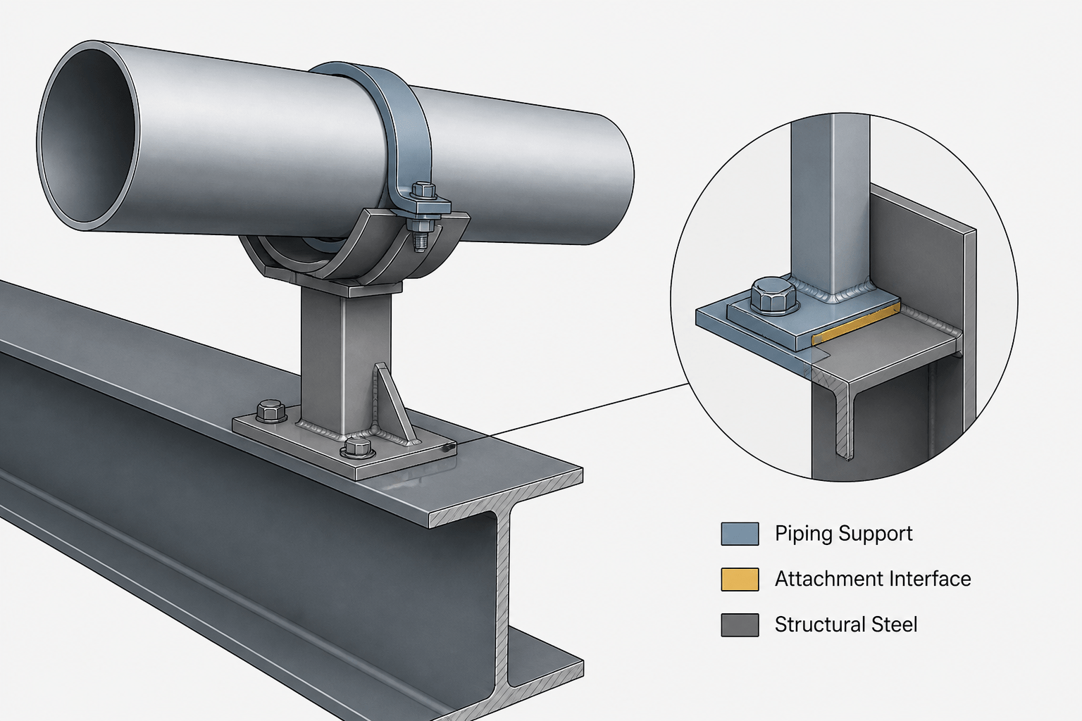
Support attachment details are the point where piping layout becomes multidisciplinary coordination. A symbol beneath a pipe may identify a support, but it does not necessarily explain how that support bears on steel, connects to concrete, or transfers restraint forces into the surrounding structure.
For useful CAD documentation, show the physical interface, identify the responsible design package, and make the support function understandable to the people reviewing, fabricating, installing, and maintaining the system. The following guidance develops that approach without treating a piping detail as a substitute for structural or equipment design.
Why piping support attachment details matter
A pipe support is not complete when the support symbol appears beneath the pipe. The drawing also needs to communicate how the support connects to steel, concrete, equipment, or another supporting structure. That interface affects constructability, access, inspection, field fit-up, and the way responsibility is divided between piping and structural disciplines.
In CAD, a support attachment detail should answer a practical question: what carries the pipe load, where does that load enter the structure, and what information does the next discipline need to verify the connection? The drawing does not need to become a structural calculation package, but it should make the physical arrangement and design boundaries clear.
This guide explains a drafting workflow for support attachment details, including steel members, pipe racks, platforms, concrete surfaces, equipment foundations, and miscellaneous support steel.
Separate the pipe support from the supporting structure
A common documentation error is treating the entire arrangement as one undifferentiated support. In practice, the piping deliverable may define the pipe shoe, clamp, guide, trunnion, or saddle while the structural deliverable defines the beam, column, bracket, base plate, anchor arrangement, or concrete attachment.
Use drawing graphics, tags, and notes to show that boundary. For example, a pipe support tag can identify the piping support assembly, while a separate steel mark identifies a structural member or bracket. A note can state that the supporting steel is shown for coordination and remains subject to structural design or confirmation. The exact wording should follow the project’s document responsibilities.
This separation prevents two opposite problems:
- Under-documentation: The pipe support is shown, but the attachment point and supporting member are unclear.
- Over-documentation: The piping drawing appears to define a structural connection that has not been checked by the responsible structural designer.
Identify the support attachment condition
Before detailing the connection, classify the physical condition. The same pipe support symbol may require different information depending on what it bears against.
| Attachment condition | What the CAD detail should communicate |
|---|---|
| Supported on a steel beam | Beam identity, support location, bearing or welded interface, and access for installation |
| Attached to a pipe rack member | Rack member reference, orientation, elevation relationship, and whether the support is fixed, guided, or allowed to slide |
| Connected to a concrete surface | Surface or foundation reference, attachment zone, base arrangement, and responsibility for anchors or embeds |
| Attached to a platform or walkway | Supporting member identification, clearance from walking surfaces, and coordination with access and handrails |
| Mounted from a miscellaneous bracket | Bracket mark, orientation, connection interface, and any required field-adjustment allowance |
| Supported from equipment or a vessel | Equipment reference, nozzle or shell interface, and confirmation that the support concept is accepted by the equipment discipline |
This classification is also useful when building a support library. A generic “support on steel” block is rarely sufficient by itself; it should have fields for the supporting member, support tag, elevation, orientation, and connection status.

Show the load path without turning the detail into a calculation
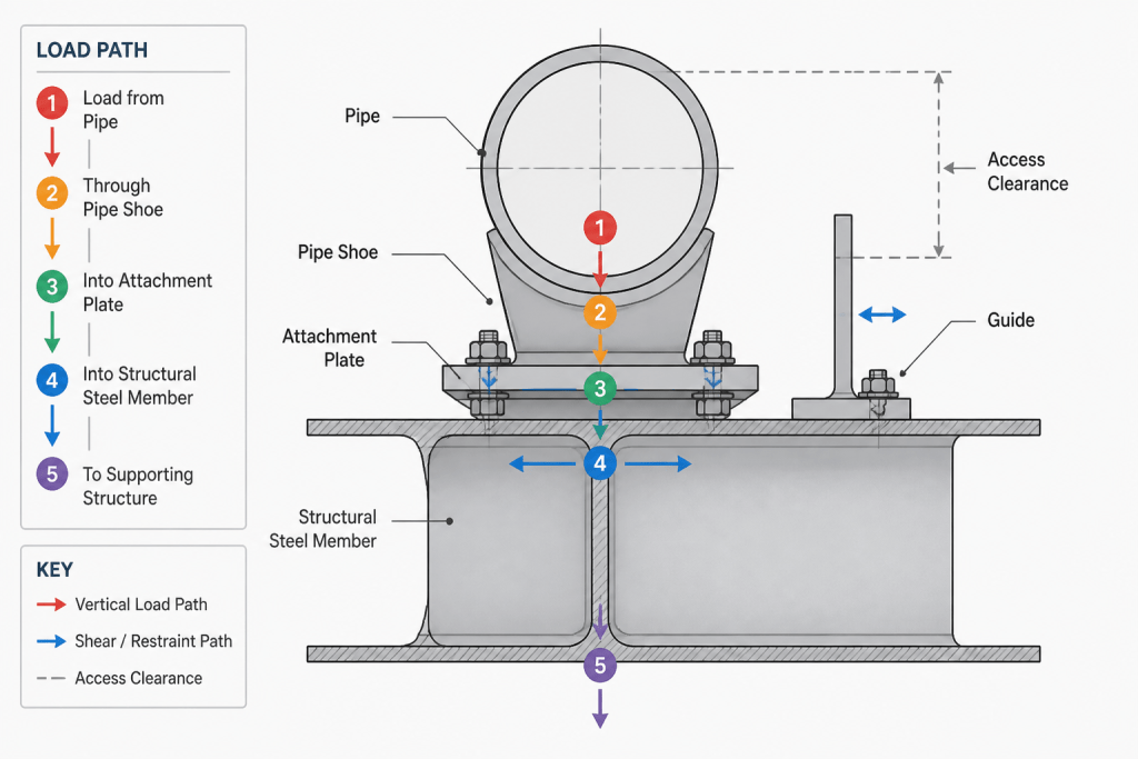
The load path is the physical sequence through which forces travel from the pipe to the supporting structure. A clear detail usually shows the pipe, the support component, the attachment plate or clamp where applicable, and the supporting member. It should also indicate whether the connection is bearing, welded, bolted, clamped, or anchored.
Do not assume that a visible contact point explains the load path. For example, a support resting on a beam may need a plate or shoe to distribute bearing. A guide may contact a structural bracket laterally but not carry the same vertical function as the primary support. A clamp may restrain movement while a separate support carries weight.
Use section views or enlarged details when the plan view cannot distinguish these functions. A small callout can identify the primary vertical support, lateral restraint, sliding interface, or attachment hardware without adding unnecessary geometry to the main isometric.
Useful graphical distinctions
- Use a clear break or boundary between piping components and structural steel.
- Show hidden attachment components only when they affect interpretation, fabrication, or installation.
- Use different line weights or layers for pipe, support hardware, existing steel, and new steel.
- Identify sliding or guided interfaces with a note or symbol that matches the project convention.
- Use section indicators when the attachment direction is not obvious in plan or elevation.
Coordinate orientation, elevation, and member identity
A support attachment can look correct in an isolated detail and still fail coordination if its orientation is ambiguous. The support should be located relative to the pipe centerline, the supporting member, and the project coordinate or elevation system used on the drawing.
Check whether the support is centered on the beam, offset toward one flange, attached to a web, or connected to a bracket projecting from the member. Do not infer the member identity from appearance alone. Include the structural mark, grid reference, support elevation, or other project-approved identifier needed to find the same item in the structural model or drawing.
For sloping or offset piping, show the relationship between pipe elevation and support elevation carefully. A support may be level while the pipe slopes, or the support top may follow the pipe orientation. These are different physical conditions and should not be represented by a generic symbol that hides the distinction.
Detail attachments to steel and concrete carefully
Steel interfaces
For steel attachments, identify the member and show the interface type. A welded bracket, bolted clip, beam seat, and pipe clamp are not interchangeable drafting representations. Where the structural connection is outside the piping designer’s scope, show the intended interface and use a responsibility note rather than inventing connection dimensions or weld information.
Check for conflicts with flange access, insulation, fireproofing, adjacent supports, maintenance platforms, and steel stiffeners. A support that fits the pipe but blocks bolt removal or inspection access is not a complete layout.
Concrete interfaces
For concrete-mounted supports, distinguish the support base from the concrete surface. Show the foundation, pedestal, slab, or wall reference as applicable, along with the support location and orientation. Anchor selection, embedment, reinforcement coordination, and concrete capacity may belong to another design package; the piping drawing should identify the required interface without presenting unverified values.
Pay attention to edge conditions, nearby openings, drains, curbs, and waterproofing details. These items frequently affect whether a proposed support can be installed as drawn.
Use notes that define assumptions and open items
Support details often depend on information that is not finalized when piping CAD work begins. Instead of silently assuming an arrangement, record the open item in a controlled manner. A useful note may identify the required structural confirmation, field verification, equipment-owner approval, or anchor coordination.
Keep notes specific. “Verify support” is weak because it does not identify what must be checked. A stronger project-style note would identify the supporting member, attachment concept, missing reference, or design responsibility. The final wording should match the project’s review and approval process.
Also distinguish between existing, new, and temporary conditions. Existing steel may require field measurement. New steel may require a structural drawing reference. Temporary erection steel may need removal or turnover information. These conditions should not share the same graphics without labels.
CAD review checklist for support attachment details
- Is the pipe support tag associated with the correct pipe segment?
- Is the supporting structure identifiable in the model or drawing set?
- Does the detail show the actual attachment or bearing condition?
- Are primary support, guide, anchor, and restraint functions distinguished?
- Is the support orientation clear in plan, elevation, or section?
- Are insulation, coating, fireproofing, and corrosion-protection interfaces addressed where relevant?
- Can installers access the connection, fasteners, weld area, and inspection surfaces?
- Are structural design responsibilities and unresolved interfaces clearly noted?
- Do support schedules, model properties, detail callouts, and isometrics use the same support identifier?
- Have clashes with platforms, ladders, cable trays, drains, equipment, and neighboring pipe been reviewed?
Make the attachment detail useful across the project
A good support attachment detail is more than a drawing embellishment. It connects the piping model to structural steel, equipment, construction, inspection, and future maintenance information. The best workflow starts by identifying the support function and attachment condition, then adds only the geometry and notes needed to make that condition verifiable.
Keep the pipe support data synchronized across the CAD model, support schedule, isometric, and structural coordination documents. When an attachment changes, update the tag, location, orientation, and responsibility notes together. This reduces field interpretation and makes design reviews more efficient without pretending that a piping detail replaces structural engineering.
How to review a support attachment detail
A practical review can follow the load path from the pipe outward. Start with the pipe and ask what component actually supports or restrains it. Then identify the attachment surface, supporting member, and final connection into the structure. This sequence helps distinguish a primary support from a guide, anchor, clamp, or other restraint.
The review should also separate three kinds of information: geometry, coordination data, and design responsibility. Geometry shows the physical arrangement. Coordination data identifies the member, elevation, orientation, and related model or drawing references. Responsibility notes identify which discipline must confirm anchors, welds, bolts, concrete capacity, equipment acceptance, or other connection requirements.
Common interpretation problems
- A support symbol is shown without a recognizable bearing or attachment interface.
- A guide or lateral restraint is mistaken for the component carrying the pipe weight.
- Existing steel and proposed support steel use similar graphics without status labels.
- The detail shows a connection concept but does not identify the supporting member or reference location.
- Insulation, fireproofing, access, or maintenance clearance is omitted from the coordination review.
These problems are usually resolved by combining an appropriate view with concise notes. Use a section or enlarged detail when the attachment direction is hidden in plan. Use tags and member marks consistently so the support can be traced between the CAD model, isometric, schedule, and structural coordination documents.
Why attachment details support better project decisions
A clear interface detail helps reviewers decide whether the proposed arrangement can be coordinated before fabrication or field installation. It exposes questions about access, existing conditions, equipment approval, structural confirmation, and temporary work instead of leaving those questions to installers.
It also improves change control. When a beam, bracket, equipment interface, or pipe elevation changes, the affected support tag and responsibility note can be reviewed with the geometry. That makes the detail a useful project record while preserving the boundary between piping drafting and engineering verification.
Frequently asked questions
What should a piping support attachment detail show?
It should show the pipe support, the supporting surface or member, the physical attachment or bearing condition, the support orientation, and the identifiers needed to coordinate the arrangement with other drawings or models.
Should piping drawings define the complete structural connection?
Not unless that responsibility is explicitly assigned and the connection has been designed and checked by the responsible discipline. A piping drawing can show the intended interface and identify open design items without inventing unverified connection information.
How can a CAD detail distinguish a support from a guide?
Use graphics, notes, tags, or section views to identify the function. A primary support carries the intended vertical load, while a guide or restraint may control movement in another direction. The detail should make those roles readable.
When is a section view necessary?
A section view is useful when the plan or elevation does not clearly show whether the support bears on a beam, connects to a web or flange, projects from a bracket, or interfaces with a concrete surface.
What should be checked before issuing the detail?
Confirm the support tag, member identity, orientation, elevation relationship, attachment concept, access for installation and inspection, nearby interferences, and responsibility for structural, concrete, anchor, or equipment verification.