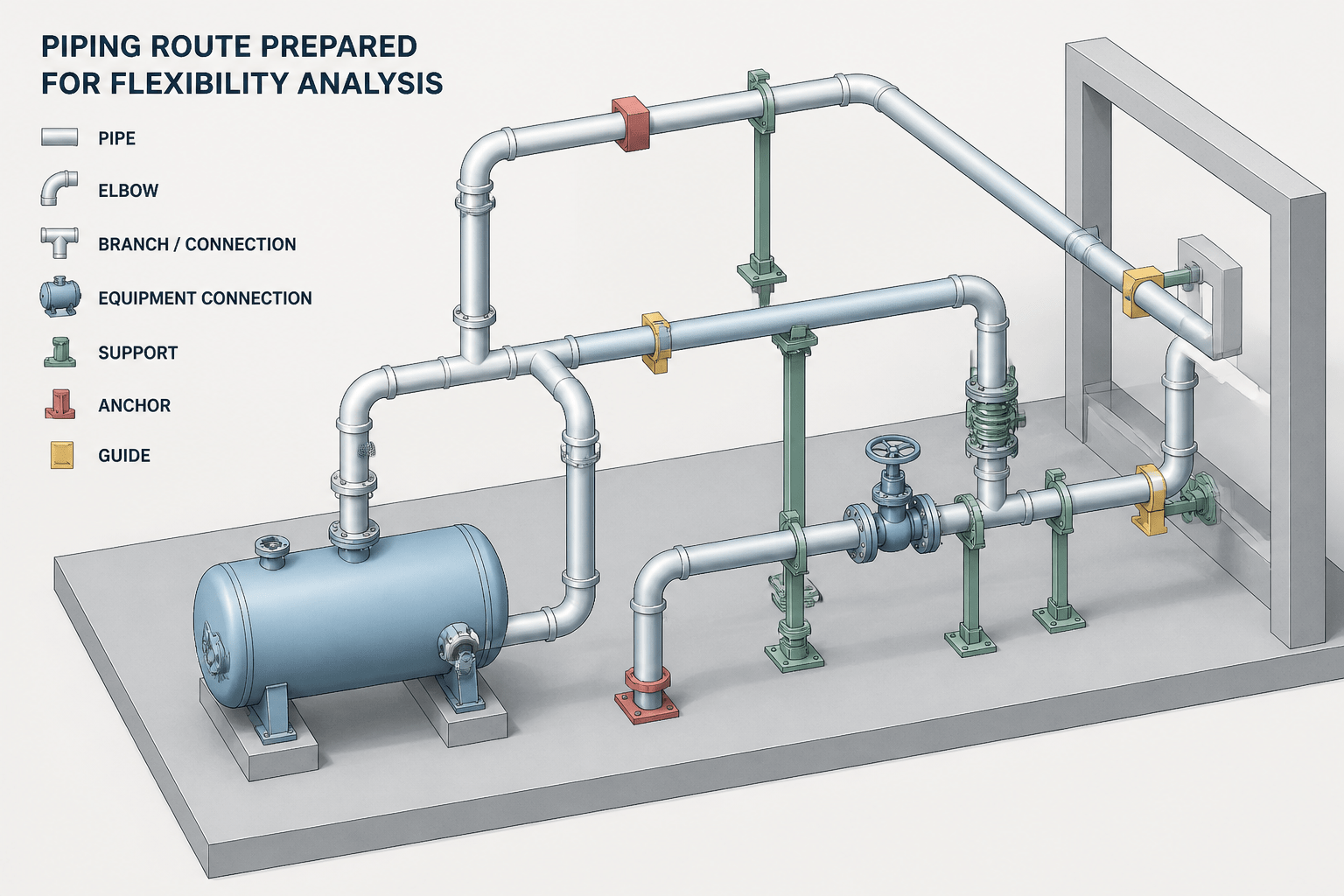
A piping flexibility analysis is only as dependable as the information transferred into the analysis model. CAD provides the physical arrangement, but it must also communicate support intent, connection boundaries, route changes, and the assumptions that affect movement.
This guide explains how to prepare a reviewable CAD handoff for thermal movement evaluation. It focuses on traceability between the layout, analysis model, support information, equipment interfaces, and design revisions so that reviewers can identify differences without reconstructing the designer’s intent.
Piping flexibility analysis in CAD is not just a matter of exporting a centerline model. The analysis model must represent the physical piping route, connection points, restraints, operating conditions, and movement assumptions clearly enough that another engineer can review and use the information without guessing.
CAD remains the visual and coordination reference, while flexibility software or engineering calculations evaluate displacement, restraint reactions, and stress behavior. A reliable handoff keeps those two representations aligned. If a support is missing from the CAD model, a branch is connected at the wrong location, or a nozzle connection is shown with an unclear boundary, the analysis may no longer represent the intended arrangement.
What a flexibility analysis handoff must communicate
A useful handoff answers four basic questions:
- What is the piping route? The model should show the intended centerline path, fittings, branches, equipment connections, and significant changes in direction.
- Where can the pipe move? Supports, guides, anchors, line stops, restraints, and sliding interfaces must be identified consistently.
- What causes movement or loading? Operating temperature, pressure, fluid condition, insulation, occasional loads, and connection assumptions come from the design basis rather than from CAD geometry alone.
- Where does the analyzed system begin and end? Model boundaries at equipment nozzles, tie-ins, buried transitions, structural interfaces, or specification breaks should be explicit.
The goal is not to place calculation results on a drawing. The goal is to make the modeled system traceable from the drawing and its associated design data.
Start with a controlled piping route
Flexibility models are sensitive to route geometry. Elbows, offsets, branch locations, straight runs, and changes in elevation all influence how a line responds to thermal expansion and applied loads. The CAD route should therefore be checked before the analysis model is created or updated.
Use a controlled source for the route, such as an approved three-dimensional model, coordinated isometric, or explicitly identified design revision. Do not silently simplify the route during handoff. A short offset removed from the CAD model may change the available flexibility. A branch moved to a nearby location may alter local stiffness and load distribution.
When simplification is necessary, record it. A handoff note can identify omitted small-bore connections, represented valves, equivalent bends, or temporary modeling assumptions. The analyst can then decide whether the simplification is acceptable instead of discovering it during review.
Make analysis boundaries visible
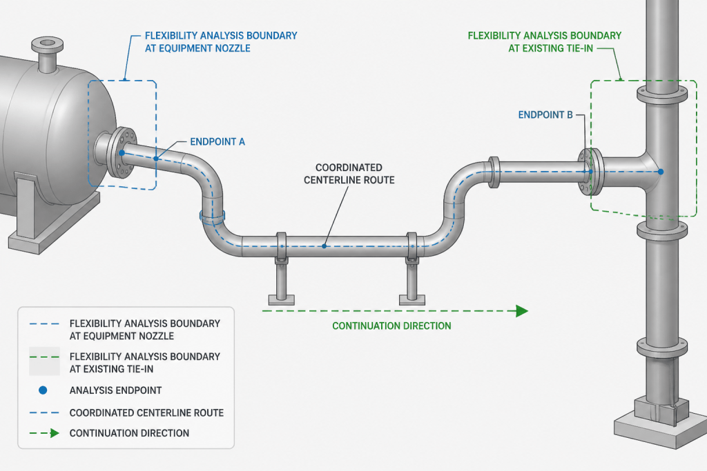
Every flexibility model needs a defined scope. A line may be analyzed between equipment nozzles, between anchors, across a piping system, or from a new tie-in to an existing system. CAD should show those boundaries with enough information to distinguish physical endpoints from arbitrary model limits.
| Boundary type | Useful CAD information | Typical review question |
|---|---|---|
| Equipment connection | Nozzle tag, connection direction, centerline location, and orientation | Does the model connect to the intended nozzle? |
| Existing piping tie-in | Tie-in identifier, continuation direction, and available interface data | What stiffness or movement is assumed beyond the tie-in? |
| Structural interface | Support or attachment location and movement direction | Is the structure treated as fixed, guided, or movable? |
| Model cutoff | Clear endpoint marker and assumption note | Why does the analysis stop at this location? |
A boundary should not be inferred only from a line ending. Use a tag, symbol, note, or model property that identifies the boundary and its associated assumption.
Coordinate supports with the analysis model
Support information is one of the most common sources of disagreement between CAD and flexibility analysis. A CAD support symbol may communicate physical intent, while the analysis model may represent that support using restraints in selected directions. Those representations must be correlated.
Give each significant support a stable identifier. The identifier should remain consistent between the three-dimensional model, isometric, support schedule, and analysis input or output. Avoid relying only on drawing coordinates or visual order, because those can change during revisions.
For each support location, review the following:
- Pipe centerline location and elevation
- Support type or functional role
- Permitted and restrained movement directions
- Vertical support or lift-off assumption
- Sliding, friction, or clearance assumption where applicable
- Connection to steel, concrete, equipment, or another pipe
- Whether the support is existing, new, temporary, or assumed
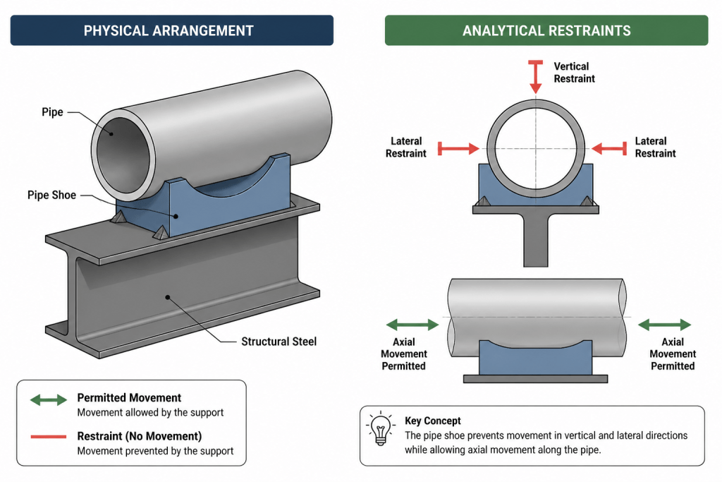
A physical support detail and an analytical restraint are related but not always identical. For example, a support may carry weight while allowing thermal movement in a horizontal direction. The CAD detail should show the physical arrangement, while the analysis data should state the assumed restraint behavior.
Show anchors, guides, and line stops by function
Similar-looking support symbols can represent very different structural behavior. A guide may limit lateral movement without stopping axial expansion. A line stop may control movement in one direction while allowing movement in another. An anchor may restrain multiple degrees of freedom, depending on the design intent and modeling assumption.
Use a support legend or schedule that explains the functional meaning of each symbol. If a symbol is project-specific, include a clear description rather than assuming that every reviewer knows the local convention.
Support locations should also be checked against nearby fittings, welds, branches, valves, and flexible elements. The analysis may use an idealized node, but the CAD model should make the physical attachment point understandable. If the support is offset from the pipe centerline or connected through a shoe, clamp, or structural member, show that relationship in the detail or associated data.
Identify loads and conditions without overloading the drawing
CAD drawings are not a substitute for the flexibility design basis. However, they should identify the information needed to connect geometry with the analysis assumptions. Depending on the project workflow, this may include line number, material or piping class, insulation condition, operating cases, design cases, test condition, fluid density, and equipment connection data.
Keep calculated values and assumptions in controlled project documents or model properties. On the drawing, use concise references such as case identifiers, support IDs, and analysis boundaries. This avoids filling the drawing with values that may become outdated while still preserving traceability.
When a line changes specification, material, temperature regime, or operating service, mark the transition clearly. Such changes may affect mass, stiffness, allowable conditions, or the interpretation of the analysis model. The exact engineering treatment belongs to the responsible analysis procedure, but the CAD model should not hide the transition.
Coordinate equipment and nozzle assumptions
Equipment nozzles are often treated as analysis boundaries, but their flexibility is not automatically known from a CAD connection. Confirm the nozzle location, orientation, projection, connection type, and any available equipment-interface assumption before using the model for review.
Where an analysis depends on nozzle flexibility, equipment movement, or a connected vessel model, identify that dependency in the handoff. Do not represent a nozzle as fully fixed merely because the CAD model shows a rigid connection. Conversely, do not imply flexibility without an engineering basis.
A practical CAD review can compare the nozzle tag and centerline against the equipment drawing, check the connection direction, and verify that the piping route reaches the correct interface without an unmarked offset or disconnected segment.
Use a revision-safe handoff workflow
Flexibility analysis and CAD development often proceed in parallel. A disciplined revision workflow prevents the analysis from becoming disconnected from the latest route.
- Identify the approved CAD revision and analysis revision.
- Compare line routes, branches, fittings, endpoints, and support identifiers.
- Record geometry changes that may affect flexibility or restraint behavior.
- Review additions and removals of supports, guides, anchors, and line stops.
- Confirm that operating cases and boundary assumptions remain applicable.
- Return analysis recommendations to CAD as traceable actions, not informal geometry edits.
- Recheck the updated model and close the revision loop.
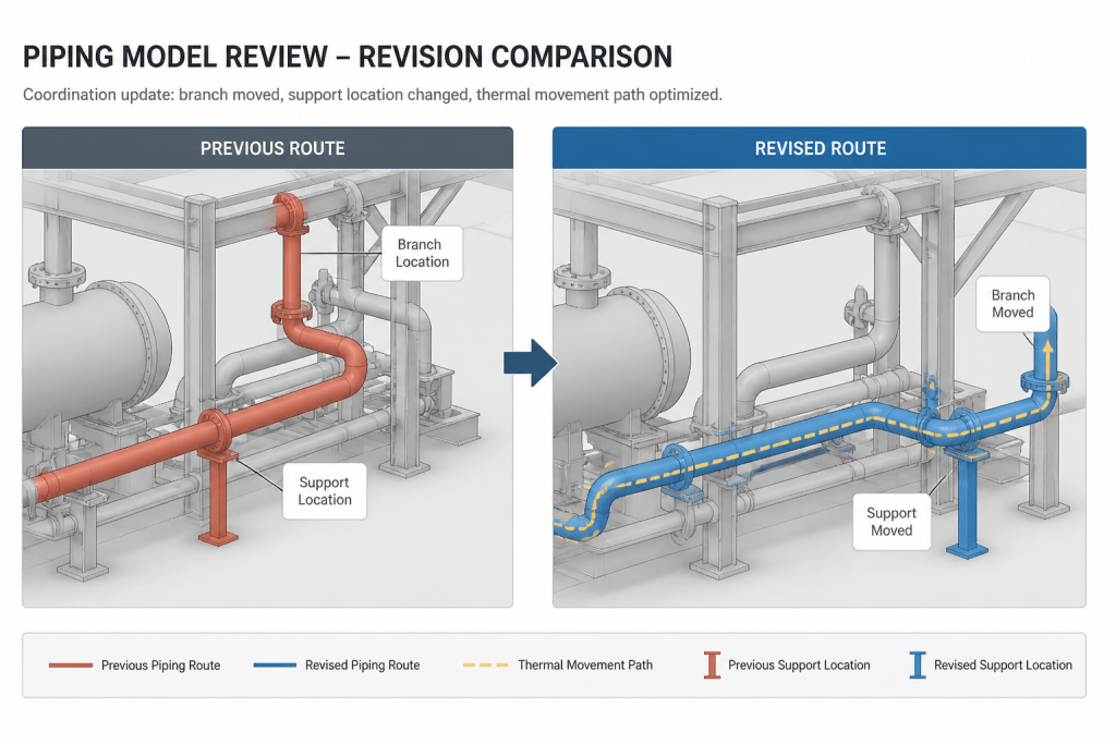
A useful comparison focuses on engineering significance rather than only on object counts. A changed elbow, moved branch, new support, or altered equipment connection may matter more than many unchanged components.
Final CAD checklist for flexibility review
- Is the analyzed route traceable to a controlled CAD revision?
- Are model boundaries identified and explained?
- Do support IDs match between CAD, schedules, and analysis records?
- Are restraint functions described rather than shown only by ambiguous symbols?
- Are equipment nozzles and tie-ins correctly located and oriented?
- Are specification, material, insulation, and service transitions visible?
- Are simplifications, omitted items, and assumptions documented?
- Can a reviewer distinguish physical support details from analytical restraints?
- Are analysis recommendations linked to specific CAD locations?
When these checks are complete, the CAD model becomes a reliable communication layer between layout, piping design, structural support design, and flexibility engineering. It does not replace the calculation, but it makes the calculation easier to build, review, revise, and relate back to the physical piping arrangement.
Why the CAD handoff matters
Flexibility review is a coordination task as well as a calculation task. The analyst needs a route that matches the intended piping arrangement, while the CAD and piping teams need analysis results that can be related back to identifiable physical locations. Clear tags, boundaries, support identifiers, and assumption notes provide that connection.
A visually complete model can still be incomplete for analysis. A support symbol may not explain which movement is restrained, and a nozzle connection may not show whether the equipment interface is treated as fixed or flexible. The handoff should therefore distinguish what is physically modeled from what is assumed for calculation.
Separate geometry from engineering assumptions
CAD is especially useful for describing centerlines, fittings, branches, elevations, equipment interfaces, and support locations. Other information, such as operating cases, restraint behavior, material treatment, fluid condition, and equipment flexibility, belongs in the controlled design basis or analysis record. The handoff should connect these sources without duplicating values that can become outdated.
This separation also makes review more efficient. A reviewer can inspect the route and interfaces in the model, then trace each condition to its applicable analysis case or project document. If an assumption changes, the responsible record can be revised without relying on an unexplained drawing edit.
What reviewers should compare
- Route continuity: Confirm that branches, offsets, elbows, elevation changes, and equipment connections correspond between the CAD model and analysis representation.
- Functional restraints: Check that guides, anchors, line stops, sliding supports, and other restraints have consistent identifiers and clearly described behavior.
- Boundary intent: Verify that nozzles, tie-ins, structural interfaces, and model cutoffs are identified rather than inferred from geometry.
- Revision significance: Focus on changes that can alter flexibility, restraint behavior, load transfer, or equipment interaction, even when the overall model appears similar.
These checks help establish whether the analysis model represents the intended physical system. They do not replace engineering judgment or the responsible flexibility calculation.
Frequently Asked Questions
Why is a centerline export not enough for piping flexibility analysis?
A centerline describes route geometry but does not fully communicate supports, restraint functions, connection boundaries, operating assumptions, or simplifications. Those items are needed to understand how the modeled piping can move and where loads are transferred.
What should be included at a flexibility analysis boundary?
Identify the physical endpoint, its tag or reference, its orientation where relevant, and the assumption applied beyond the boundary. This may include an equipment nozzle, existing piping tie-in, structural interface, buried transition, or documented model cutoff.
How should CAD support symbols be coordinated with analytical restraints?
Assign stable support identifiers and describe the functional behavior of each support. The CAD model should show the physical attachment, while the analysis record should state which movement directions are restrained, permitted, or subject to a specific assumption.
Should every calculated value be placed on the CAD drawing?
No. Drawings should provide concise references to cases, support IDs, boundaries, and controlled design information. Detailed calculated values and assumptions should remain in the applicable project records or model properties so they can be maintained consistently.
How should omitted or simplified components be documented?
Record the simplification in a handoff note or controlled model information. Identify omitted connections, represented components, equivalent geometry, or temporary assumptions so the analyst can assess whether the simplification is acceptable.
What is the best way to manage CAD and analysis revisions?
Identify the applicable revisions, compare route and support changes, review altered boundaries and equipment interfaces, and document engineering-significant differences. Recommendations should return to CAD as traceable actions rather than informal geometry changes.