
Clear piping specification breaks help engineers, designers, fabricators, and reviewers understand where governing requirements change along a line. The best CAD annotation does more than mark a location: it connects the physical interface to the applicable specification, component data, ownership, and downstream documentation.
This guide explains how to locate, assign, annotate, and review specification breaks without confusing them with line-number changes, drawing boundaries, or ordinary changes in geometry.
A piping specification break is the point where one section of a piping system changes from one approved piping specification to another. The change may involve material, pressure class, wall thickness, corrosion allowance, joining method, valve requirements, gasket selection, or another controlled design property.
In CAD, the break is not merely a line on a drawing. It is a coordination point between the model, piping specification, bill of materials, fabrication documents, and related engineering information. If the break is missing, vague, or placed at the wrong component, downstream users may select the wrong item or misunderstand where a requirement begins and ends.
What a piping specification break means
A piping specification, sometimes called a line class or piping class, defines the component rules for a particular service or design condition. It can control which pipes, fittings, flanges, valves, gaskets, bolting, branch connections, and specialty items are permitted.
A specification break occurs when the governing requirements change along the route. Common causes include:
- A change in material or corrosion-resistant alloy requirement.
- A change in pressure-temperature service or flange class.
- A transition between plant-owned piping and equipment-supplied piping.
- A change from process piping to utility piping.
- A change in joining method, such as a transition between welded and threaded components.
- A change in insulation, lining, cleanliness, or fabrication requirements that is controlled by the piping specification.
- A battery-limit or package boundary where different design documents govern each side.
The exact meaning depends on the project documentation. A specification break does not automatically mean that the adjacent pipes have different outside diameters, and a visible fitting or flange does not necessarily mark the break. Always verify the controlling specification and the project drafting convention.
Where should the break be placed?
The most useful location is the point where responsibility or component selection changes. In many cases, the break is shown at a flange, valve, branch connection, weld, or other identifiable joint. However, the correct location depends on which item belongs to each specification.
| Situation | CAD question to resolve | Typical documentation need |
|---|---|---|
| Flanged connection | Which specification governs each flange, gasket, and bolting set? | Show the break at the agreed interface and identify any special connection note. |
| Butt-welded transition | Which side supplies the pipe and fitting at the weld? | Show the weld location and make the specification assignment unambiguous. |
| Valve boundary | Is the valve assigned to the upstream, downstream, or separate equipment specification? | Use the valve tag and notes to clarify ownership and material requirements. |
| Equipment nozzle | Where does piping design responsibility end? | Coordinate the nozzle, mating flange, gasket, and bolt-up requirements with equipment documents. |
| Branch connection | Does the branch fitting follow the run specification or branch specification? | Check the branch schedule, fitting type, and specification assignment together. |
Do not place a break simply because the line changes direction or passes through a drawing sheet boundary. The break should correspond to a real change in requirements or responsibility, not to a drafting convenience.
How to show specification breaks in a piping drawing
1. Identify the governing line or system information
Start with the line list, P&ID, piping material specification, model data, or other approved source used by the project. Confirm the line number, service, size, insulation status, and specification assignment. If the source documents disagree, do not resolve the conflict by guessing from the geometry.
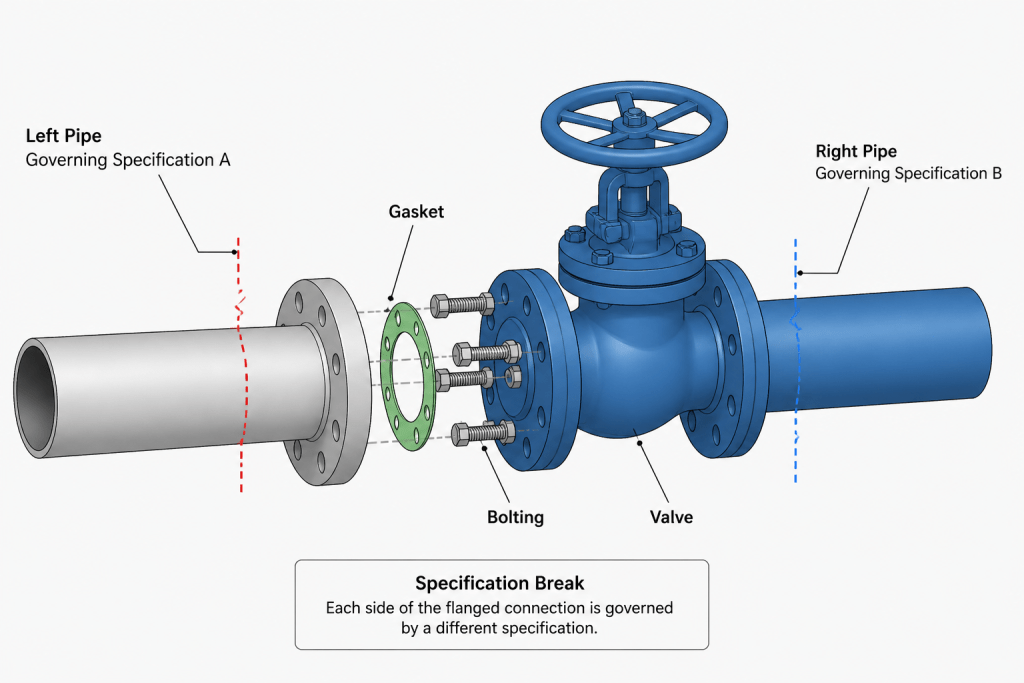
Pay attention to the direction of the line. A break may be recorded as a change from one specification to another, but the drawing should make it clear which specification applies on each side. Use labels, line data, or specification fields rather than relying on the reader to infer direction from the view.
2. Locate the physical interface
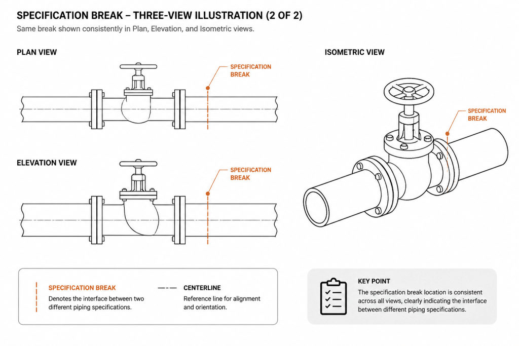
Find the real transition in the model or drawing. It may be a flange face, weld, valve end, equipment connection, branch fitting, or package limit. Check that the selected interface is represented consistently in plan, elevation, section, and isometric views where it appears.
If the interface is hidden or crowded, use a leader, note, or enlarged detail. A specification break that is technically present but visually buried is difficult to verify.
3. Assign each component correctly
Review the components immediately around the break. These commonly include pipe ends, fittings, flanges, gaskets, bolts, valves, reducers, branch fittings, and specialty items. The most frequent drafting error is to show the break but leave the adjacent components without a clear specification assignment.
Where an item is shared by two requirements, document the project rule. For example, a flange pair may be selected as a matched connection, while a valve may have its own material and rating designation. Do not assume that the nearest line-specification label answers every component question.
4. Use consistent annotation
Apply the project convention for specification labels, break symbols, leaders, notes, and model properties. Keep the annotation close enough to the interface to avoid ambiguity, but do not cover weld symbols, dimensions, equipment tags, or flow arrows.
On an isometric, a short leader or break note can identify the transition without interrupting the pipe line. On a plan or elevation, a station or coordinate reference may help locate the interface. In a 3D model, use searchable component properties as well as visible drawing annotation when the software supports them.
CAD checks that catch common mistakes
A good specification-break review checks both geometry and data. Use the following workflow before issuing a drawing:
- Trace the line: Follow the route from its origin to its destination and mark every documented specification change.
- Compare views: Confirm that the break appears at the same physical interface in plan, elevation, section, and isometric views.
- Check continuity: Make sure the pipe segment before and after the break is not accidentally assigned the same specification throughout the model.
- Review boundary components: Check flanges, gaskets, bolting, valves, branch fittings, and weld locations at the transition.
- Verify the bill of materials: Confirm that the component quantities and descriptions reflect the intended specification assignments.
- Check fabrication documents: If the line will be split into spools, verify that the specification break and any field connection are coordinated with spool boundaries.
- Test filters and reports: Use model queries or CAD schedules to find components with missing, conflicting, or unexpected specification data.
- Review ownership: Confirm whether the interface belongs to piping, equipment, a vendor package, or another discipline.
Common specification-break errors
Showing a break without identifying both specifications
A symbol alone may tell the reader that a change exists, but not what governs either side. Use clear labels or model data that identify the adjacent specifications according to the project standard.
Putting the break at the wrong side of a flange
Flanged connections contain multiple items with potentially different procurement or ownership rules. If the break is placed at the center of the flange symbol without clarifying the flange pair, gasket, and bolting arrangement, the drawing may remain open to interpretation.
Relying on color as the only indication
Color can help during model review, but it is not a reliable sole method for issued drawings, printed sets, grayscale viewing, or accessibility. Support color coding with labels, properties, or notes.
Allowing a specification break to disappear in a spool drawing
Spool drawings may simplify the overall line, but they still need enough information to show material boundaries, field connections, and component ownership. Coordinate the spool split with the specification assignment instead of treating the two as unrelated decisions.
Confusing a specification break with a line-number change
A line number can remain the same across a transition, or a project may assign a new line number for reasons unrelated to the piping specification. Treat line identification and specification assignment as separate checks unless the project rules explicitly link them.
A practical review sequence
For a fast but reliable review, first highlight every specification change in the source data. Next, locate each interface in the CAD model and confirm that the physical joint exists. Then inspect the boundary components and verify their properties. Finally, review the drawing at its intended output scale to ensure the annotation remains readable.
The goal is not to add more symbols. The goal is to make the change in requirements traceable from the source information to the model, drawing, bill of materials, and fabrication package. When a reader can identify where the specification changes, which components are affected, and which document controls the decision, the CAD detail is doing its job.
Why specification-break clarity matters
A specification break can affect more than the pipe segment itself. Boundary items such as flanges, gaskets, bolting, valves, branch fittings, welds, and specialty components may require individual review. If the CAD model shows only a symbolic break without clear component assignments, procurement, material takeoff, fabrication, and field installation teams may interpret the interface differently.
Model data and drawing annotation should agree
Visible notes and symbols are important for issued drawings, but model properties and searchable data provide another layer of control. A reliable workflow checks that the specification information is consistent across the line list, P&ID, piping material specification, CAD model, isometric, bill of materials, and fabrication documents.
When project documents disagree, the correct response is to identify the discrepancy and obtain an approved resolution. Geometry alone should not be used to infer which specification governs an interface.
Review the interface, not just the break symbol
Pay particular attention to the physical connection where requirements change. Confirm what happens to each adjacent item and whether the interface is controlled by piping, equipment, a vendor package, or another discipline. This is especially important at equipment nozzles, flanged joints, valves, branches, and spool boundaries.
A useful review question is: can another person determine which specification applies on each side, which components are included, and which document controls the decision? If not, improve the annotation or supporting model data before issue.
Frequently asked questions
Is a piping specification break the same as a line-number change?
No. A line number and a piping specification serve different identification purposes. A line may retain its identification across a specification transition, or a project may change the line number for reasons unrelated to the specification. Follow the project rules and check both items independently.
Does a change in pipe direction indicate a specification break?
No. A change in direction is a geometric feature, not proof that the governing piping requirements have changed. Place the break where the specification, responsibility, or component-selection rule actually changes.
Where should a break be shown at a flanged connection?
Show it at the agreed interface and clarify which specification governs each flange, gasket, and bolting arrangement. The project rule may assign the connection items to one side, both sides as a matched set, or a separate requirement.
Can color coding replace a specification-break note?
No. Color may support model review, but it should not be the only indication in issued drawings. Labels, leaders, notes, and searchable component properties provide information that remains usable in grayscale, printed documents, and accessibility-focused workflows.
How should specification breaks be checked in a CAD model?
Trace the complete line, compare the break location across views, inspect boundary components, review model properties and schedules, verify the bill of materials, and coordinate the result with spool and fabrication documents. Resolve conflicting source information rather than guessing from the model.