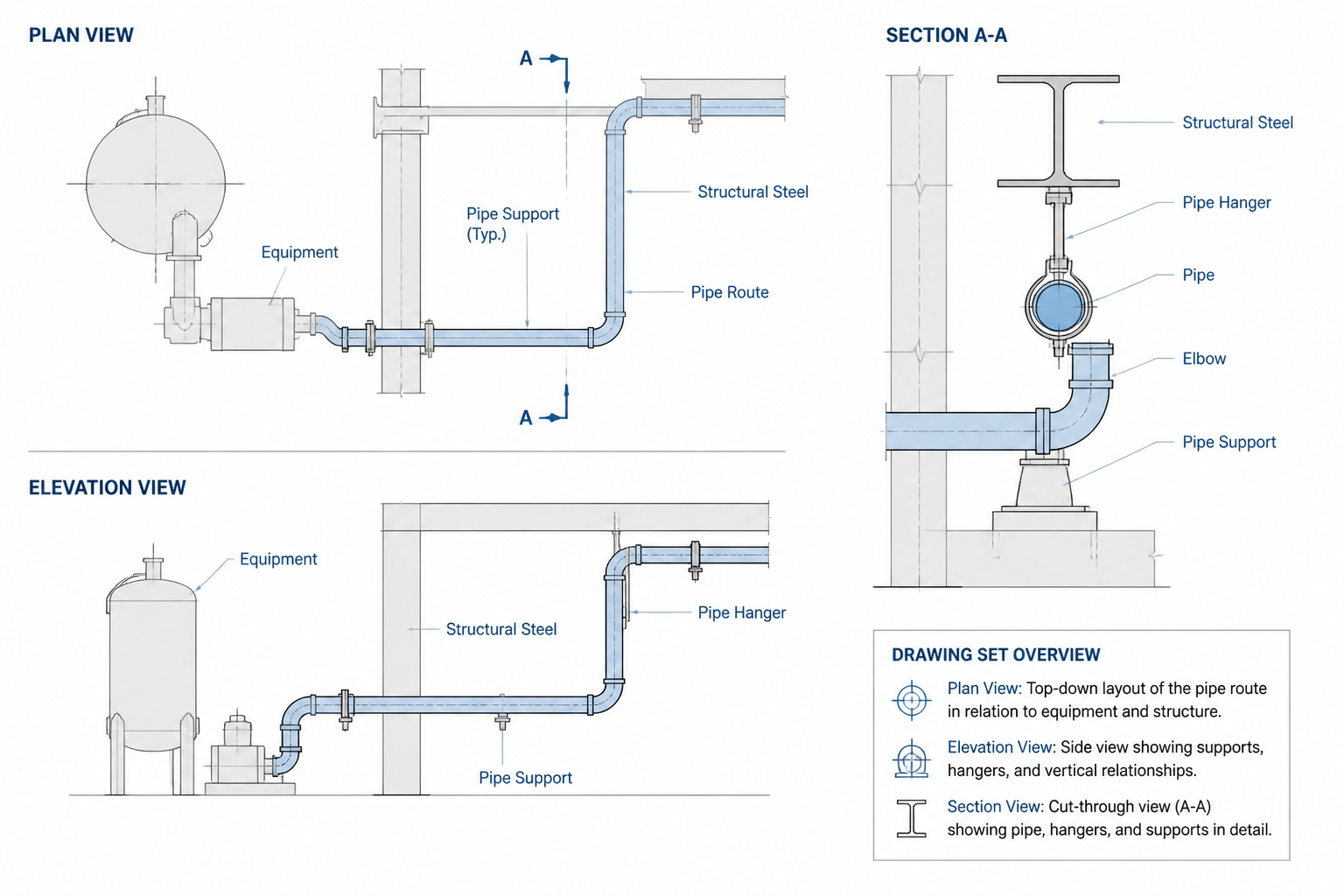
Coordinating piping in CAD is not only a matter of drawing lines between connection points. A route can appear clear in plan while its vertical relationship, access requirements, or interaction with structure remains uncertain. Using complementary views gives reviewers a more dependable way to interpret the layout.
This practical guide is intended for piping drafters, designers, reviewers, and CAD coordinators who need to communicate three-dimensional routing through clear two-dimensional documentation. It explains how to decide when a plan, elevation, or section adds useful information and how to keep those views consistent during revisions.
Piping drawings rarely communicate a complete installation through one view. A plan view may show horizontal routing, while an elevation or section reveals vertical changes, clearances, and connections that are hidden from above. Using these views together is essential when preparing, reviewing, or revising piping CAD drawings.

This guide explains how plan, elevation, and section views work together in a practical drafting workflow. It focuses on drawing clarity and coordination rather than project-specific design requirements. Always verify dimensions, component data, and applicable project criteria against the approved design documents and the relevant piping terminology references.
What each piping view communicates
Each view is a different projection of the same three-dimensional arrangement. The goal is not to repeat every item in every view. The goal is to show enough information for the reader to understand location, direction, elevation, and interfaces without guessing.
- Plan view: Shows the arrangement as seen from above. It is useful for horizontal routing, equipment locations, branch directions, access paths, and relationships between adjacent lines.
- Elevation view: Shows height and vertical relationships. It can clarify changes in elevation, overhead routing, drops, risers, and connections to nozzles or other systems.
- Section view: Shows a cut through a congested or important area. It is useful when overlapping lines, structural members, supports, or equipment interfaces cannot be understood clearly in plan or elevation.
A view should be included because it answers a coordination question. Adding views without a purpose can make a drawing harder to read and can introduce conflicting or outdated information.
Start with the drawing purpose and source information
Before creating geometry, identify what the drawing must prove. A general arrangement drawing may need to show route and equipment relationships. A fabrication-oriented detail may require more precise connection, spool, or weld information. A layout used for coordination may emphasize clearances and interfaces with steel, equipment, ducts, or electrical systems.
Collect the controlling information before drafting:
- Approved equipment locations and nozzle orientations
- Line numbers, service information, and material specification references
- Pipe sizes, schedules, and component descriptions from the project data
- Structural backgrounds and relevant architectural or mechanical references
- Known elevations, orientation references, and project coordinate conventions
- Existing conditions, if the drawing represents a modification or tie-in
For dimensional checks, link the drawing to the appropriate pipe dimensions and schedule data rather than relying on a remembered value or an unverified block. Component geometry should also be checked against the applicable fitting or flange reference page before it is used in a final drawing.
Build the plan view first when horizontal routing controls the layout
In many layouts, the plan view is the best starting point because it establishes the horizontal path and the relationship between major items. Begin with a clean reference layer or external reference for equipment, structures, and existing piping. Then add the primary pipe centerlines and identify the direction of flow or the relevant connection sequence.
Keep the first pass simple. Show the route, major changes in direction, branches, and connection points before adding detailed fittings or annotation. This makes it easier to identify an incorrect route or an unresolved interface early.
When drafting the plan view, check the following:
- Are equipment and nozzle locations aligned with the approved background?
- Can the reader distinguish new piping from existing or reference piping?
- Are parallel lines separated enough to remain legible at the plotted scale?
- Do branches connect to the intended line and point in the correct direction?
- Are access zones, maintenance areas, and structural obstructions represented where relevant?
- Does the route leave unresolved vertical changes that require an elevation or section?
Use consistent line types, colors, and layer names according to the project CAD standard. Graphic styling should support the information hierarchy; it should not be used to hide uncertain or incomplete design decisions.
Use elevations to explain vertical routing
An elevation view is often needed when a plan view shows two lines crossing but does not reveal whether they are at different heights. It also clarifies risers, drops, overhead runs, sloped segments, and connections located above or below the primary plan plane.
Choose an elevation direction that presents the most useful information. The view may be aligned with a pipe run, an equipment face, a structural grid, or a congested corridor. Label the viewing direction clearly when there is any possibility of confusion.
In an elevation, show the features that establish vertical intent:
- Pipe centerlines and changes in elevation
- Equipment nozzles and connection points
- Structural members that control available space
- Relevant supports, guides, anchors, or attachment points
- Slopes or directional changes when they affect installation or operation
- Clearance-critical components such as valves, instruments, and removable items
A common mistake is to create an elevation as an isolated sketch. Instead, project key points from the plan view or use shared coordinates so that the two views remain synchronized. If the plan route changes, update the elevation and check the affected section views at the same time.
Add sections only where they resolve ambiguity
A section view should answer a specific question that plan and elevation cannot answer efficiently. Typical questions include: Which line passes in front? Is a pipe inside or outside a structural frame? How are several lines arranged through a narrow opening? Does a valve or flange require space that is not visible in the other views?
Place the section line in the view where the cut location is easiest to understand. Use arrows and a section identifier that match the resulting view. The cut should pass through the relevant geometry; a decorative section that does not reveal new information adds clutter without improving coordination.
In a congested section, use line weights and hidden-line conventions carefully. Distinguish cut elements from elements beyond the cutting plane, and avoid showing every background object with equal visual emphasis. Add callouts for items that are important but not obvious from the graphic representation.
Coordinate annotations across views
Annotations should help the reader move between views. Use matching line numbers, equipment tags, section identifiers, and detail references. A component shown in plan and elevation should have enough context in both views to prevent misidentification.
Good annotation practice includes:
- Dimension from stable references rather than from temporary construction geometry.
- Use a consistent datum or elevation reference throughout the drawing set.
- Place dimensions outside congested geometry when possible.
- Avoid repeating the same dimension in multiple views unless the repetition prevents a likely error.
- Use notes to identify intent, not to compensate for missing geometry.
- Keep tags readable at the intended plotted size.
For detailed connection identification, coordinate the view with the project’s pipe end connection references and flange data pages. The drawing should identify the connection type and component intent, while the reference data supplies the authoritative dimensional information.
Common coordination errors
| Error | Why it causes problems | Useful check |
|---|---|---|
| Plan and elevation use different route geometry | The reader cannot determine which view is current. | Compare every change in direction, branch, and endpoint between views. |
| Crossing lines are shown without elevation information | A crossing may be mistaken for an intersection. | Add an elevation, section, or clear level annotation. |
| Section arrows are unclear | The reader may look in the wrong direction or cut through the wrong area. | Verify arrow direction, identifier, and cut location. |
| Background references dominate the piping | Important pipe geometry and tags become difficult to read. | Reduce background contrast and use a clear layer hierarchy. |
| Component blocks are used without checking orientation | The graphic may show a plausible but incorrect connection arrangement. | Check the block against the component reference and actual design intent. |
A practical final review sequence
Review the drawing in the same order a new reader would use it. First confirm the title, view labels, north or orientation reference, and drawing limits. Next compare equipment and structural references with the current source files. Then trace each major pipe route through plan, elevation, and section views.
For each line, verify its endpoints, branches, vertical changes, visible components, and annotations. Check that the line number and specification reference remain consistent. Review congested areas at the plotted scale, not only while zoomed in inside CAD. Finally, inspect the sheet for orphaned dimensions, duplicate tags, stale references, missing section labels, and geometry that extends outside the intended view.
A coordinated piping drawing does more than display geometry. It gives the reader a reliable way to understand three-dimensional routing through complementary two-dimensional views. When each plan, elevation, and section has a clear purpose—and when all three are updated from the same source information—the result is easier to review, detail, revise, and use in downstream CAD work.
How to use this guide during CAD coordination
Use the existing drawing information as the project-specific authority, then apply the guidance here as a review framework. The most useful question is not whether a drawing contains many views, but whether each view resolves a location, routing, clearance, or interface question that another view cannot show clearly.
Separate geometry checks from presentation checks
First confirm that the route, endpoints, branches, elevations, and connection interfaces agree with the approved project information. Then review presentation: line hierarchy, labels, dimensions, section markers, background references, and plotted readability. A visually polished drawing can still contain inconsistent geometry, while a technically correct layout can be difficult to use if the views are poorly coordinated.
Use reference data deliberately
Pipe dimensions, schedules, fittings, flanges, and end connections should be verified from the applicable project data and reference pages rather than inferred from a generic CAD block. Related resources such as pipe dimensions and schedules, pipe end connection types, and flange references can support that check without replacing approved design information.
Review the drawing as a downstream user
Ask whether another person could trace a line from its origin to its destination, understand changes in direction and elevation, identify relevant components, and locate the correct section or detail without guessing. This reader-focused check is especially valuable before issuing a revised CAD file, coordination background, or drawing package.
Frequently asked questions
What is the difference between a piping plan and an elevation?
A plan shows the arrangement as viewed from above, making it useful for horizontal routing and relationships between nearby items. An elevation shows vertical relationships, such as risers, drops, overhead runs, and connection heights. They describe the same layout from different directions.
When is a piping section view necessary?
Add a section when the plan and elevation do not clearly explain a congested or coordination-critical area. A section can clarify relative position, structural interfaces, support conditions, and access around components. It should resolve a specific question rather than repeat information without purpose.
Should the plan, elevation, and section use the same pipe geometry?
Yes. The views should be coordinated representations of the same approved layout. Changes to a route, endpoint, branch, or vertical transition should be checked across all affected views so that one view does not remain based on outdated geometry.
What information should be checked before drafting?
Check the approved equipment and nozzle information, line and service data, pipe and component references, structural backgrounds, orientation conventions, known elevations, and existing conditions where applicable. Project documents remain the controlling source for design decisions.
How can a drawing make crossings easier to understand?
A plan crossing does not by itself prove that two lines intersect. Add an elevation, section, or clear level information when the relative height is important. The selected view should make the spatial relationship clear without relying on guesswork.
Why do CAD blocks need review before use?
A block may look plausible while using the wrong orientation, connection arrangement, or representation for the project. Compare it with the applicable component reference and confirm that it matches the intended design before treating it as authoritative.