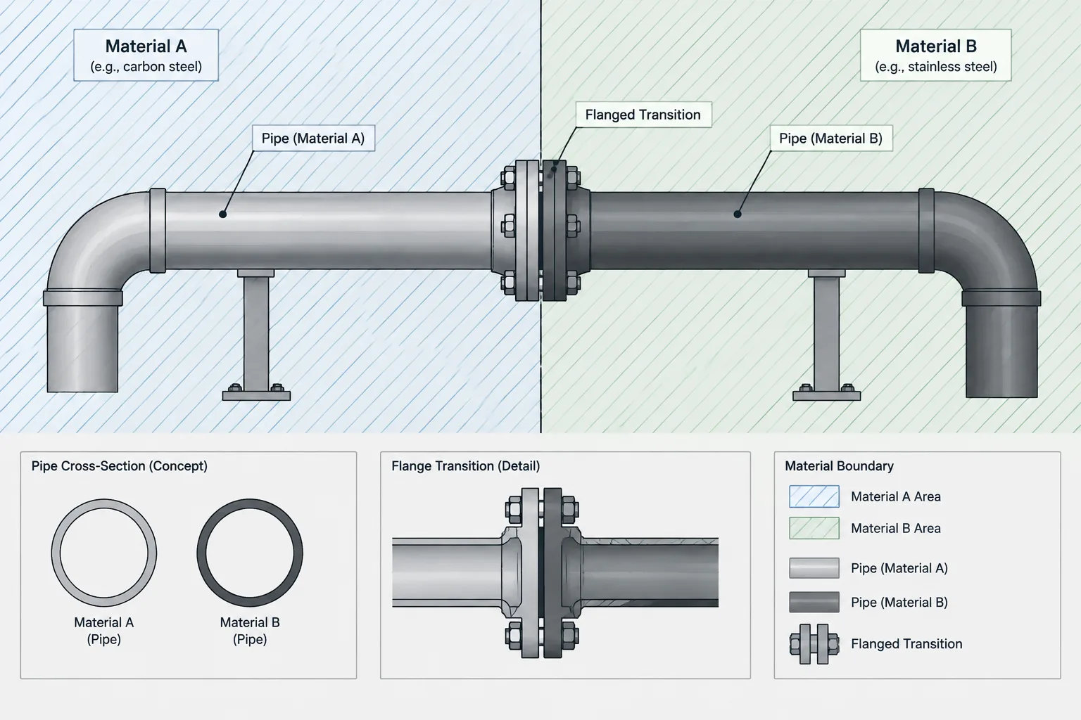
Piping specification breaks in CAD require coordination between engineering requirements, physical connection design, model data, and drawing annotation. A visible symbol alone is not enough: the model must establish where one piping class stops, where the next begins, and which rules govern every component at the interface.
This guide explains how to distinguish a specification break from related line, size, connection, and testing boundaries. It also provides a practical workflow for locating the break, assigning transition components, checking connection compatibility, and reviewing downstream CAD outputs.
A piping specification break marks a boundary where the governing piping material specification, or piping class, changes. The line may remain physically continuous, but the rules used to select pipe, fittings, flanges, valves, gaskets, bolting, branch connections, and other components are no longer the same on both sides.
In CAD, that boundary must be more than a note placed near a line. Its exact location affects component selection, connection compatibility, bills of material, isometric extraction, purchasing, fabrication, testing, and field installation. A vague or misplaced break can assign a transition component to the wrong class or create a joint whose two sides have not been checked together.
What a piping specification break actually controls
A piping class is a project-defined collection of component selection rules. It may reflect material, pressure-temperature capability, corrosion allowance, end connections, flange facing, gasket type, branch construction, valve requirements, lining, or service-specific restrictions. The controlling data must come from the approved project documents rather than assumptions based on a class name.
A specification break identifies where one set of those rules ends and another begins. It does not necessarily indicate:
- A change in nominal pipe size
- A physical gap in the pipe
- A change in line number
- A process isolation point
- A test boundary
- A change in design pressure or temperature
Any of these conditions may occur at the same location, but they are separate concepts. For example, a line can retain its line number while changing piping class, or it can receive a new line number without changing its component specification.
Why the exact boundary location matters
A specification change rarely occurs in an abstract length of line. It normally has to be associated with a physical component, joint, or defined connection point. That association determines which class governs the parts immediately around the transition.
Consider a flanged connection between two classes. The designer must establish which specification controls each flange, the gasket, the bolting, and any companion components. A break symbol placed generally across the pipe does not answer those questions. Similarly, if the break is shown at a valve, the project must define whether the valve belongs to the upstream class, the downstream class, or a separate transition assembly.

There is no universal drafting shortcut that correctly assigns every transition component. Ownership should follow the project’s piping specifications, line data, P&ID conventions, and engineering decisions.
Common locations for specification breaks
Equipment nozzles and package interfaces
A class boundary may occur where plant piping meets an equipment nozzle or a vendor-supplied package. The nozzle connection is a physical interface, but it is also a data-ownership interface. The equipment side may be governed by vendor requirements while the connected piping is governed by the plant piping class.
The CAD model should distinguish the nozzle from the first plant piping component and preserve the defined connection point. Designers should verify flange compatibility, facing, connection type, bore relationship, gasket requirements, and bolting rather than assuming that matching nominal sizes create a valid joint.
Valves and specialty components
Some projects place a class break at an isolation valve, control valve assembly, pressure-relieving device, meter assembly, or other specialty item. This can be convenient because the component provides a visible physical boundary, but its ownership must still be explicit.
A specialty assembly may also include reducers, mating flanges, gaskets, bolts, vents, drains, and instrument connections. Treating the tagged item as the entire transition can leave those surrounding parts incorrectly classified.
Material or corrosion-service transitions
A specification break may separate different base materials, linings, coatings, or corrosion-control strategies. Such transitions can require more than a change in CAD properties. Joint design, welding details, electrical isolation, contamination control, and fabrication sequencing may need engineering review.
The model should represent the selected physical transition rather than simply changing the pipe color or layer at an arbitrary coordinate.

Aboveground and underground interfaces
Buried and exposed piping may use different component rules, coatings, joint types, or installation details. The boundary is often coordinated with grade, a wall penetration, a sleeve, or a defined transition fitting. Grade alone should not be treated as the specification break unless project documents establish it as the controlling location.
Branch connections
A branch may use a different class from its run pipe. In that case, the team must determine whether the break occurs at the run wall, at the outlet end of a branch fitting, at a flange, or at another defined connection. This decision affects the branch fitting, reinforcing detail, first branch component, and generated material list.
Spec break, line break, and size change compared
| Condition | What changes | CAD concern |
|---|---|---|
| Specification break | Component selection rules or material class | Assign the boundary and transition parts correctly |
| Line number break | Line identity or process-document designation | Keep tags, reports, and drawing continuations synchronized |
| Size change | Nominal size | Use the correct reducer, reducing fitting, or component end size |
| Connection change | Joint or end type | Model the required adapter or transition assembly |
| Test boundary | Defined test extent | Coordinate isolation and test documentation separately |
Several conditions can coincide, but combining them into one generic symbol obscures what each boundary controls. Clear documentation allows reviewers and downstream users to understand whether they are looking at a material-class transition, a process identity change, or both.
A practical CAD workflow
Start with the controlling documents
Review the P&ID, line list, piping material specifications, equipment data, valve and specialty-item data, and project drafting procedures. Resolve differences before routing or assigning components. A class shown on a line list should not be silently overridden because a nearby modeled line uses another class.
Place a precise boundary node
Associate the break with a defined port, joint, face, weld, or other connection point. Avoid floating annotation that can move independently of the transition. If the CAD system supports connected object properties, both sides of the node should retain their respective class data.
Assign the transition components deliberately
Determine which class governs every item at the interface. This includes components that are easy to overlook, such as gaskets, bolting, branch outlets, small-bore connections, companion flanges, and short pipe pieces.
If a component does not belong cleanly to either class, document it as an engineered transition item rather than forcing an inaccurate class assignment merely to satisfy software validation.

Check physical compatibility
Class assignment alone does not prove that two components can connect. Review end type, facing, nominal size, outside diameter basis, bore, wall thickness, pressure class where applicable, gasket arrangement, bolting, and any material compatibility concerns. The required checks depend on the actual connection.
Verify outputs
After modeling the break, inspect the isometric, bill of materials, line report, and any interface or connection report. Confirm that:
- The break appears at the intended physical location.
- Components on each side carry the correct class.
- The transition item is not omitted or counted twice.
- Gaskets and bolting follow the approved joint definition.
- Line numbers and service data remain correct.
- Drawing notes agree with model properties.
Drafting and annotation practices
A specification break symbol should be visible without concealing the joint it describes. Identify the classes on both sides or use another project-approved notation that makes the direction of the change unambiguous. On congested drawings, a leader should terminate at the actual boundary rather than at a general area of pipe.
Do not rely solely on color. Colors can be lost in monochrome plots, exports, screenshots, and fabrication prints. The class should also exist as readable object data or text.
Where a transition requires a special detail, link the drawing callout to that detail and identify the components included in its scope. Avoid broad notes such as “change material here” when the fabrication team needs to know exactly which weld or joint establishes the change.
Frequent review problems
- Break shown only on the P&ID: The 3D model and isometric continue with one class.
- Break placed inside a component: The software cannot determine which class owns the component.
- Transition hardware omitted: The model changes properties without showing the physical adapter or joint.
- Class name treated as sufficient: Compatibility is assumed without checking the actual connection data.
- Branch inherits the run class: The branch line data calls for another class, but inherited model properties are never corrected.
- Manual text disagrees with object data: The drawing looks correct while reports and material lists remain wrong.
Final review principle
A piping specification break is both a data boundary and a physical interface. Good CAD documentation connects those two ideas: it places the boundary at an identifiable joint, assigns every adjacent component intentionally, and verifies that drawings and material outputs reflect the same decision. When the correct location or component ownership is uncertain, flag the interface for engineering resolution rather than hiding the uncertainty behind a generic break symbol.
Specification-break handoff checklist
Before releasing a model or drawing, review the interface as a coordinated package rather than as an isolated annotation. The person receiving the design should be able to identify the governing class on each side and understand how the physical transition is assembled.
- Boundary definition: Confirm that the break terminates at a recognizable port, joint, face, weld, or connection point.
- Component ownership: Establish which specification governs each adjacent pipe, fitting, flange, valve, gasket, bolting item, branch component, and specialty item.
- Connection review: Verify that the selected ends and joint arrangement are physically compatible rather than relying only on matching class labels.
- Model properties: Check that object data agrees with visible notes, symbols, and line identification.
- Output review: Inspect isometrics, material reports, connection reports, and other generated deliverables for missing, duplicated, or misclassified items.
- Open decisions: Record unresolved ownership or transition questions for engineering review instead of assigning a convenient but unsupported class.
Managing changes after the boundary is established
A specification break should be included in normal model-change control. Moving a valve, replacing a transition fitting, revising a package interface, or changing branch geometry can shift the intended boundary or alter component ownership. Updating only the drawing note may leave model properties and reports inconsistent.
When an interface changes, recheck both sides of the connection and regenerate the relevant outputs. This helps keep the P&ID intent, line data, model objects, isometric annotation, and material information aligned through design revisions.
Frequently asked questions
Can a piping line keep the same line number across a specification break?
Yes. Line identity and piping-class assignment are separate controls. Project documents may retain the same line number while changing the component-selection rules at a defined interface.
Should the specification break be placed at the center of a valve?
Not unless the approved project method explicitly defines that location and establishes ownership of the valve and its connecting parts. A boundary placed inside a component can create ambiguity in CAD data and material reporting.
Does a change in pipe size automatically create a specification break?
No. A size change concerns nominal size, while a specification break concerns the governing component rules. Both changes may occur together, but each must be documented according to its own purpose.
Is changing the CAD layer or color enough to represent the boundary?
No. Graphic differences can help reviewers, but the class assignment should also be stored in the appropriate object data and tied to a precise physical connection. The information must remain understandable in reports and monochrome outputs.
Which class owns a gasket or bolting set at a flanged transition?
That decision must come from the approved project specifications and joint definition. It should not be inferred solely from the upstream class, downstream class, or nearby annotation.
What should be done when a transition component does not fit either class?
Identify it as an engineered transition item and document its requirements explicitly. Forcing it into an unsuitable class can conceal compatibility issues and produce misleading material reports.