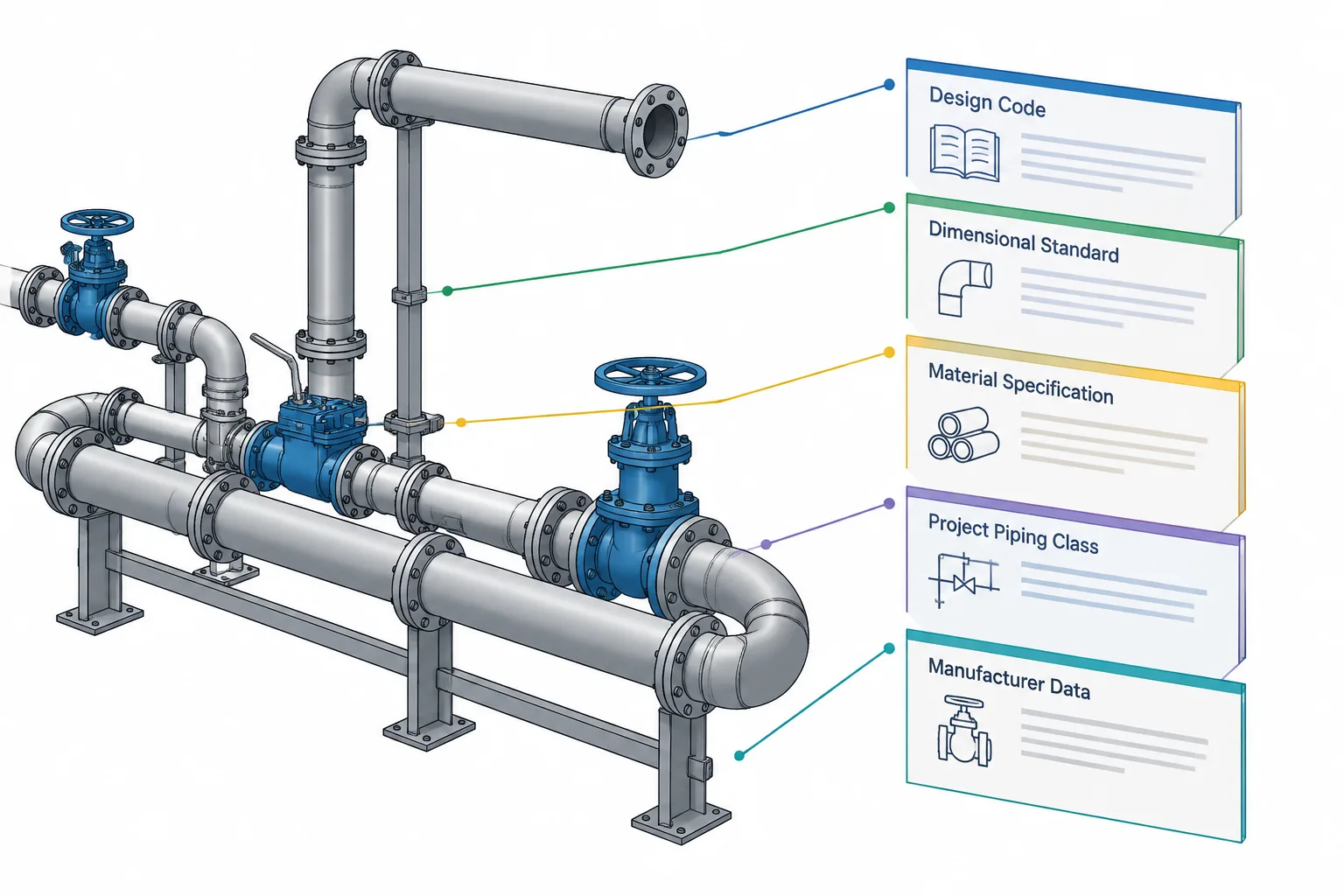
Piping codes, standards, and specifications serve related but different purposes. Correct component selection requires knowing which document governs the system, which defines the component or interface, which controls the material product, and which limits the options permitted by the project.
This guide explains that document hierarchy from a practical piping-design and CAD perspective. It can help users trace a model property, drawing note, or purchase description back to the appropriate technical authority instead of relying on geometry or terminology alone.
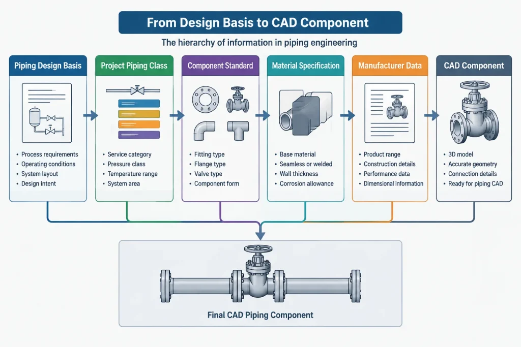
Piping projects rely on several kinds of technical documents, but those documents do not all answer the same questions. A design code may establish the overall engineering framework, while a dimensional standard defines component geometry, a material specification defines product requirements, and a project piping class limits which combinations may be used.
Confusing these roles can produce a CAD model that looks complete but is not technically traceable. A flange may have the expected nominal size yet use the wrong facing, material, bore, rating designation, or drilling basis. A pipe may have a valid material grade but an unresolved wall thickness. Understanding the document hierarchy helps designers select components correctly and helps reviewers identify which source should resolve a conflict.
The five document types commonly encountered in piping
Terminology varies among companies and industries, but most piping information comes from five broad sources.
1. Design and construction codes
A piping code provides the governing engineering framework for a defined type of service or facility. Depending on its scope, it may address subjects such as design conditions, allowable stresses, pressure design, fabrication, examination, testing, and acceptance.
The ASME B31 family is a familiar example in United States piping work, but selecting the applicable code is an engineering and contractual decision. A code is not simply chosen because a pipe or fitting appears in a particular catalog. Jurisdictional requirements, facility type, service, owner requirements, and the project contract can all affect the governing basis.
A design code generally does not function as a complete component catalog. It may recognize or reference other standards, but the designer still needs the applicable dimensional, material, and project documents.
2. Component and dimensional standards
Component standards define standardized attributes for products such as pipe fittings, flanges, valves, or threaded parts. Their scope may include dimensions, end connections, tolerances, pressure-temperature rating conventions, facing details, marking, testing, or other product requirements.
Examples commonly encountered in piping references include documents from the ASME B16 series and MSS. The exact scope must be checked rather than inferred from the document title. One standard may address geometry and ratings, while another may focus on a particular component family or manufacturing form.
For CAD work, these standards are often the source of dimensions such as center-to-end, end-to-end, face-to-face, flange thickness, hub geometry, or connection details. They should not be reduced to a single lookup value. Component type, size, class or wall designation, end form, and other qualifiers may all affect which row or figure applies.
3. Material and product specifications
Material specifications identify requirements for a product form and material grade. Depending on the specification, these requirements may address chemical composition, mechanical properties, manufacturing method, heat treatment, testing, dimensions, permissible variations, certification, or marking.
ASTM specifications are frequently referenced for piping materials in US projects. API and other organizations also publish product requirements used in particular services. A material specification is not automatically a dimensional standard for every finished component made from that material.
For example, knowing a component’s material grade does not by itself establish its end-to-end dimension, flange drilling, wall schedule, or pressure class. Those properties must come from the appropriate component standard, purchase description, piping class, or manufacturer document.
4. Project specifications and piping classes
A project piping class converts broad code and standard options into an approved component selection for a defined service range. It may identify permitted pipe, fittings, flanges, gaskets, bolting, valves, branch methods, wall requirements, corrosion allowance, end connections, and special notes.
The piping class is therefore a selection document, not merely a material list. It tells the designer which combinations the project has accepted. Two components may each comply with recognized standards but still be an invalid combination under the project class.
Project specifications may also impose requirements that are more restrictive than the baseline industry documents. The project should define document precedence and how conflicts are resolved. There is no safe universal rule that every company uses in the same way.
5. Manufacturer and vendor data
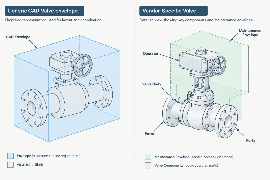
Manufacturer data becomes especially important for valves, strainers, specialty fittings, expansion devices, instruments, lined components, and proprietary equipment connections. Standardized end interfaces do not guarantee that the complete body envelope, operator location, weight, face-to-face dimension, or maintenance space is identical among products.
Generic CAD geometry can support early layout, but vendor-certified information may be needed before finalizing interfaces, supports, access, or fabrication dimensions. The model should distinguish between a representative component and a selected product.
Which document answers which question?
| Design question | Primary document type | Typical CAD or drawing result |
|---|---|---|
| What engineering rules govern the piping system? | Applicable design and construction code | Design basis, calculation criteria, examination and test context |
| What component geometry or standardized interface applies? | Component or dimensional standard | Fitting takeout, flange geometry, connection form, or valve face-to-face basis |
| What material grade and product requirements apply? | Material or product specification | Material callout and purchasing description |
| Which permitted combination should be used on this line? | Project piping class and specifications | Selected pipe, fitting, flange, gasket, bolting, and valve properties |
| What is the actual envelope of a selected specialty item? | Manufacturer or vendor data | Final body dimensions, operator orientation, weight, ports, and maintenance envelope |
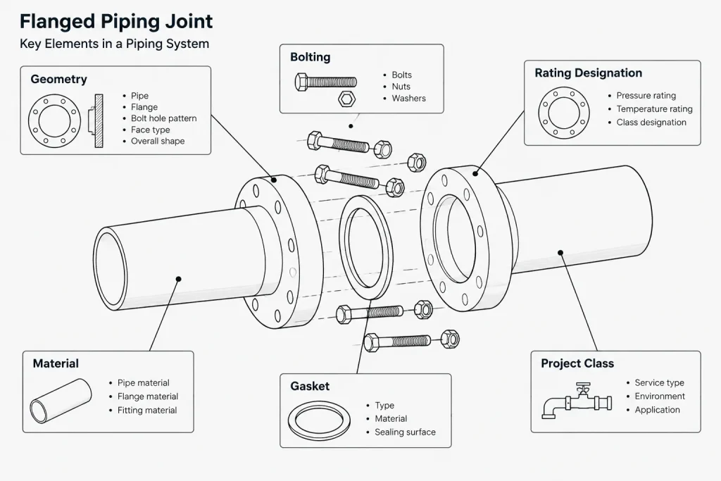
More than one source is often required. A flange selection, for example, may involve the project class for permitted type and material, a component standard for standardized geometry and ratings, a material specification for grade requirements, and vendor data for the supplied product.
How this hierarchy should appear in CAD data
A reliable piping model should retain enough metadata to explain why a component was selected. Geometry alone is a weak record because visually similar components can represent different technical requirements.
Useful component properties may include:
- Component family and type
- Nominal pipe size or nominal diameter designation
- Pipe schedule, wall series, or specified wall thickness where applicable
- Pressure class or other applicable rating designation
- End connection, facing, and end-preparation details
- Material specification and grade
- Project piping class
- Dimensional source and document revision status
- Manufacturer and model when a product has been selected
- Any assumptions used for preliminary geometry
These properties support bills of material, specification checks, model audits, and later replacement. They also make it easier to determine whether a dimensional discrepancy is a modeling mistake or the result of two different source documents.
A practical source-control workflow
- Confirm the line design basis. Identify the applicable service, design conditions, governing code basis, and project requirements before choosing components.
- Find the project piping class. Use it to determine the permitted component families, materials, wall designations, ratings, and connection types.
- Identify the dimensional authority. Record the standard, project detail, or manufacturer document used for each critical dimension.
- Separate generic and vendor-specific items. Mark preliminary component envelopes so they are not mistaken for certified product geometry.
- Control document revisions. Avoid silently combining dimensions from different revisions or from unverified secondary tables.
- Check connected interfaces. Verify bore, wall, end preparation, facing, bolt pattern basis, gasket arrangement, and mating component requirements as applicable.
- Preserve traceability. Carry the relevant specification and source fields into the model, isometric, bill of material, or component database.
Common interpretation errors
Treating a CAD library as the technical authority
A block, parametric part, or downloaded model is a representation of source data. It is not proof that the component complies with the project requirements. Library geometry should be checked against the controlled dimensional source.
Assuming nominal size proves compatibility
Matching NPS or DN labels do not establish complete compatibility. Wall thickness, bore, end form, facing, rating designation, material, gasket arrangement, and manufacturing tolerances may still differ.
Confusing pipe schedule with flange class
Pipe schedule describes a pipe wall-thickness series. Flange class is a rating designation used within the applicable flange framework. They are different properties and should occupy separate CAD database fields.
Using a material specification to determine all geometry
A material designation may define important product requirements, but it does not automatically provide every finished component dimension. Geometry must be taken from the applicable component standard or qualified product data.
Assuming standardized means universally interchangeable
Standardization improves consistency, but interchangeability still depends on the complete component description. Specialty designs, different bores, trim, operators, linings, end details, and manufacturer-specific envelopes can affect replacement and layout.
Resolving conflicts without guessing
When two sources disagree, the drafter should not choose whichever dimension best fits the model. First determine whether the documents describe the same component type, size, rating, material form, and revision. Then consult the project-defined order of precedence and submit the discrepancy to the responsible engineering or document-control function.
The final CAD model should reflect a resolved technical decision, not hide the conflict through stretching, scaling, or custom geometry. Recording the dimensional source and approval status gives future users a clear path back to the design basis.
The central principle is simple: codes establish the engineering framework, standards define recognized products and interfaces, material specifications control product requirements, project classes select permitted combinations, and manufacturer documents describe the actual supplied item. Good piping documentation keeps those roles connected without treating them as interchangeable.
Building a reviewable document trail
A useful review trail connects each important model or drawing property to the document that controls it. The record does not need to reproduce proprietary requirements. It should identify the source clearly enough for an authorized reviewer to confirm the selection in the controlled project documents.
For each component, reviewers should be able to distinguish among the governing design basis, the project-approved selection, the standardized interface, the specified material product, and any vendor-specific geometry. Keeping those fields separate prevents one source from being used outside its intended scope.
Questions for a model or drawing review
- Authority: Is the controlling document identified rather than merely implied by a catalog description?
- Applicability: Does the cited source cover the actual component family, connection, material form, and service context?
- Selection: Does the project piping class permit the complete component description?
- Geometry: Is the modeled shape based on the applicable dimensional source or clearly marked as preliminary?
- Interfaces: Have mating ends, facings, bores, gaskets, bolting, and adjacent components been reviewed together where applicable?
- Revision control: Can the team identify the document status used when the component was created or approved?
- Vendor status: Is representative geometry distinguishable from information for the selected product?
What to record when clarification is required
When documents appear inconsistent, a technical query should describe the affected line or component, the conflicting requirements, the model or drawing impact, and the decision needed. The discrepancy should remain visible until the responsible project authority resolves it. This is safer than editing geometry to make the conflict disappear.
After resolution, update both the geometry and its associated properties. A corrected shape with outdated specification metadata can still produce an incorrect bill of material, component schedule, or future replacement decision.
Frequently asked questions
Is a piping code the same as a component standard?
No. A piping code establishes an engineering framework for its defined scope, while a component standard addresses recognized products, interfaces, dimensions, ratings, testing, or related requirements within its own scope. A project commonly relies on both.
Does compliance with an industry standard mean a component is approved for the project?
Not necessarily. The project piping class and specifications may permit only selected materials, component types, end connections, ratings, or combinations. General standards compliance does not replace project approval.
Can a material grade determine fitting or flange dimensions?
A material grade identifies material or product requirements, but it does not automatically establish every finished-component dimension. Geometry must be verified from the applicable component standard, project detail, or qualified manufacturer data.
Which document should control when two sources conflict?
Use the order of precedence established by the project contract and controlled project procedures. First confirm that both sources address the same component description and document status, then refer unresolved differences to the responsible engineering or document-control authority.
When is generic CAD geometry acceptable?
Generic geometry can be useful for preliminary routing, arrangement, or space planning when its status and assumptions are clear. It should not be presented as certified product geometry, particularly where interfaces, access, supports, fabrication, or maintenance depend on the selected item.
Why should document sources be stored as CAD properties?
Source properties support model audits, bills of material, specification checks, change management, and future replacement. They also help reviewers determine whether a discrepancy comes from modeling, component selection, document revision, or vendor-specific design.