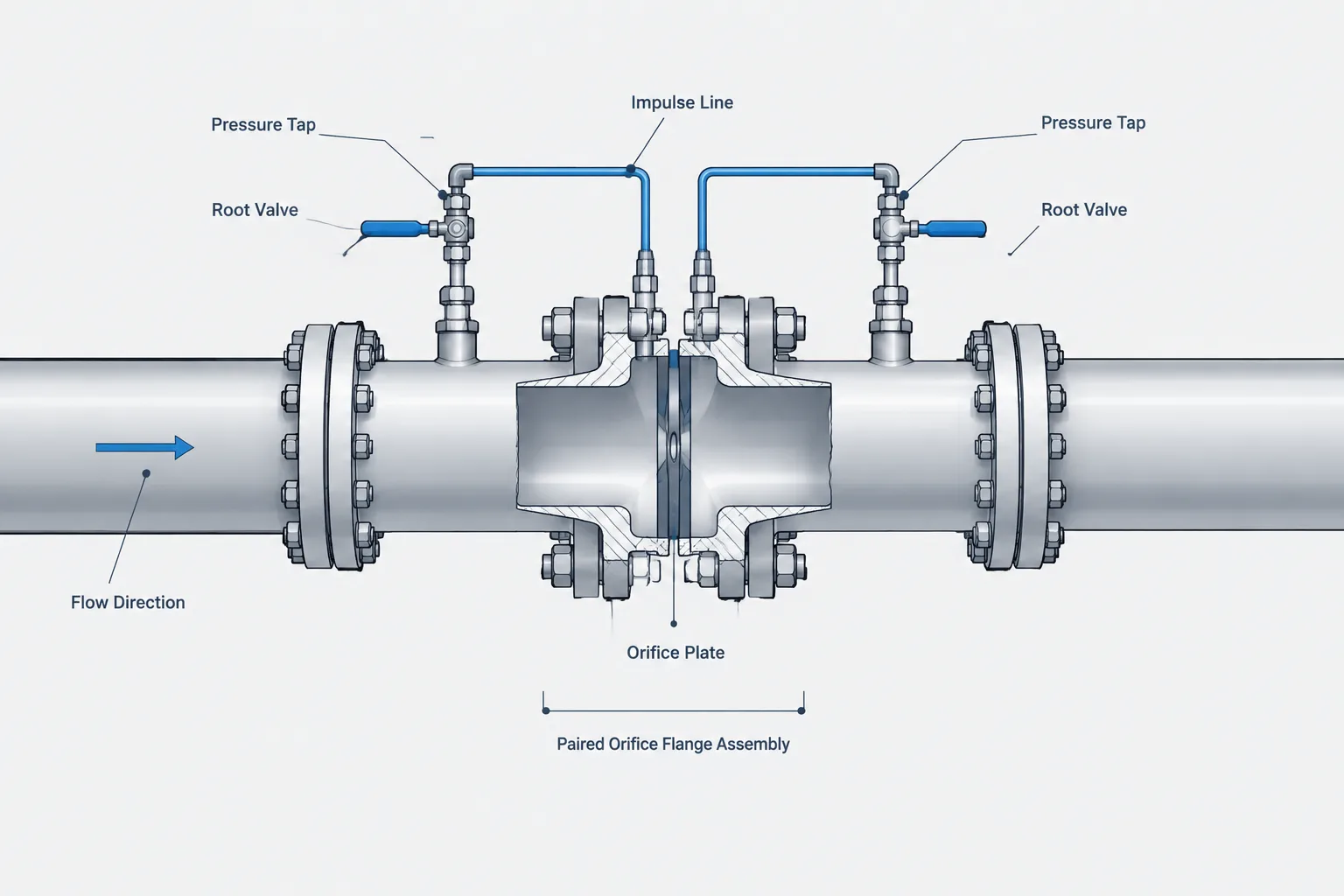
Orifice flanges in piping CAD require more control than an ordinary flanged connection. The model must communicate the relationship among the flange pair, orifice plate, pressure taps, flow direction, impulse-line interfaces, and surrounding meter run.
This guide explains the drafting and coordination issues that help prevent orientation errors, inaccessible instrument connections, incorrect joint representation, and conflicts between piping and measurement documents. Final geometry and installation requirements must remain tied to the project specification, approved engineering data, and verified supplier information.
An orifice flange assembly may resemble an ordinary flanged joint, but it performs a different project function. In addition to joining pipe, the assembly positions an orifice plate and provides pressure-tap connections used to measure differential pressure. Those added functions affect component selection, orientation, instrument routing, maintenance access, and drawing documentation.
For piping designers and CAD users, the main challenge is not simply placing two flanges around a plate. The model must represent the correct interfaces without treating every detail as generic. Flange geometry may come from an applicable dimensional reference, while the plate bore, tap arrangement, gasket stack, instrument connections, and required upstream and downstream piping are normally controlled by project engineering and verified supplier data.
What Is an Orifice Flange Assembly?
An orifice flange assembly is a paired flange arrangement designed to hold an orifice plate between the flange faces. Pressure taps communicate with the pipe bore on opposite sides of the plate. When fluid passes through the restricted opening, a pressure difference develops. Instrument tubing or impulse piping connects the taps to a differential-pressure instrument or transmitter.
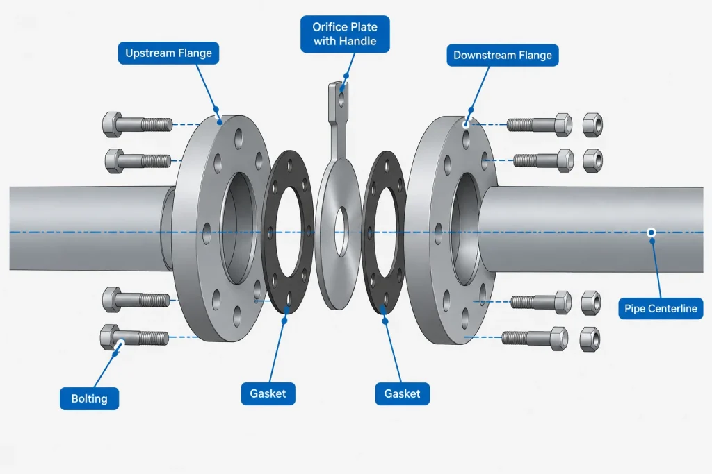
The assembly should be understood as a measurement interface rather than as two unrelated flange components. Its coordinated parts may include:
- an upstream orifice flange;
- a downstream orifice flange;
- an orifice plate selected for the measurement application;
- gaskets appropriate to the joint design;
- bolting and any project-specified plate-handling or separation features;
- pressure-tap connections, plugs, valves, or fittings;
- impulse lines leading to the instrument; and
- identification and flow-direction information.
The exact assembly depends on the piping specification, measurement design, service conditions, and purchased equipment definition. A generic CAD symbol or catalog component should not be assumed to establish the complete metering design.
How Orifice Flanges Differ from Standard Flanges
A standard line flange primarily provides a detachable pressure-containing joint. An orifice flange adds pressure-tap features and must locate a metering plate in a controlled relationship to those taps. That distinction affects both the physical component and the data attached to it.
| Feature | Ordinary flanged joint | Orifice flange assembly |
|---|---|---|
| Primary function | Connect or disconnect piping components | Hold a restriction plate and provide a differential-pressure interface |
| Pressure taps | Not normally integral to the joint function | Provided as part of the flange arrangement |
| Flow orientation | May be irrelevant for a symmetric flange pair | Important to plate identification, taps, and measurement documentation |
| Joint contents | Typically a gasket between mating faces | Includes an orifice plate and the specified sealing arrangement |
| Instrument coordination | Usually limited | Requires coordination with valves, impulse lines, supports, and transmitter location |
| Replacement control | Based mainly on flange and connected-component data | Also requires plate and metering-interface data |
Replacing an orifice flange pair with ordinary flanges in a model can therefore remove functional information even if the nominal pipe size and flange class appear unchanged.
Pressure Taps and Flange Clocking
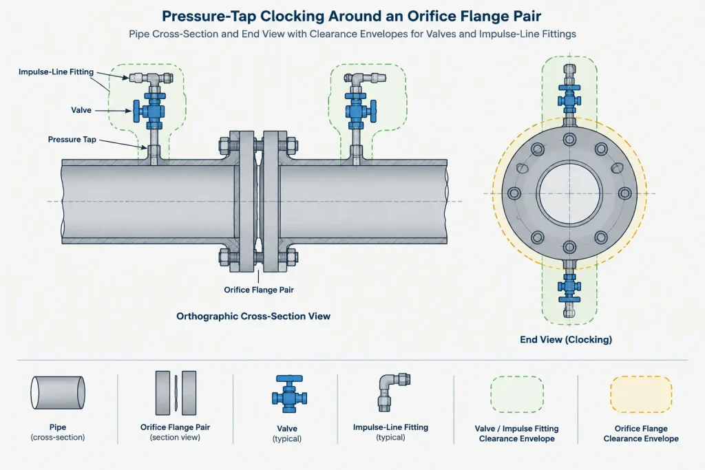
The pressure taps are among the most important geometric features to represent. Their angular position around the pipe determines where root valves, fittings, tubing, and maintenance access must be located. A model that shows the flanges but omits the taps may pass a basic line-routing review while concealing an instrument-access conflict.
Tap orientation should come from the approved project arrangement. It can depend on fluid service, instrument practice, drainage or venting needs, accessibility, and the intended impulse-line route. A convenient graphical position is not sufficient justification for choosing the clocking.
Useful CAD checks include:
- confirming that both tap connections are on the intended side or sides of the meter run;
- checking clearance for root-valve handles and installation tools;
- providing space for fittings without interference from flange bolting;
- avoiding clashes with pipe supports, insulation, steel, cable tray, and adjacent piping;
- allowing impulse lines to be routed according to the project instrument details; and
- showing the tap orientation clearly on isometrics or installation drawings.
Clocking should be stored as controlled orientation data when the CAD system permits it. Rotating only the visible tap graphics without updating connection points or metadata can create a misleading model.
Orifice Plate Orientation and Flow Direction
An orifice plate is not just a thin spacer inserted into a flange joint. Its bore, edge configuration, material, identification, and installed direction are part of the measurement design. Some plate designs are directional, while others may have installation markings that must remain visible or correspond to the process flow.
The line flow direction should be coordinated among the P&ID, line list, instrument documentation, model, and isometric. The plate tag and meter identification should also remain consistent across those deliverables. Designers should not infer the required plate direction solely from the shape of a simplified CAD object.
A useful model can show a plate handle or identification tab as an orientation feature, but its size and position should be based on verified assembly information. The handle also needs an accessible envelope. Locating it against a wall, structural member, or neighboring line can prevent plate removal or make its identification difficult to read.
Meter-Run Layout Is More Than Flange Placement
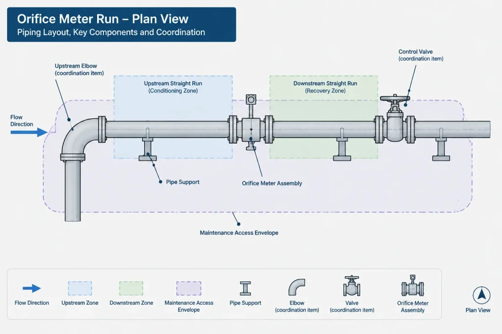
Flow-measurement performance can be influenced by the piping configuration upstream and downstream of the orifice plate. Elbows, tees, reducers, valves, and other disturbances may affect the velocity profile reaching the plate. The required meter-run arrangement cannot be established by a universal CAD rule because it depends on the measurement method, disturbance type, piping configuration, and governing project criteria.
CAD designers should therefore receive approved layout requirements from the responsible process or instrumentation discipline. The model can then preserve the required straight-run region and identify any restrictions on nearby components.
During layout review, check for:
- the correct upstream and downstream sides of the assembly;
- prohibited or controlled fittings within the defined meter-run zone;
- valves whose internal geometry or operating position could disturb flow;
- reducers or branches placed too close to the measurement point;
- adequate support without imposing an unsuitable load on the assembly;
- access to taps, plate handle, bolting, and instrument valves; and
- space to remove the plate or separate the joint using the approved maintenance method.
A straight-looking pipe segment in a model is not proof that the measurement arrangement is acceptable. The controlling distance and configuration should be recorded through project data, dimensions, notes, or designated meter-run components rather than judged visually.
Joint Stack-Up and Pipe Cut Length
The orifice plate and its sealing arrangement affect the flange-joint stack-up. Consequently, pipe cut lengths and face-to-face dimensions should be developed from the specified assembly rather than copied from an ordinary flange pair.
CAD libraries vary in how they represent this arrangement. One system may use a dedicated assembly object, while another may place two flanges, a plate, and gaskets as separate items. Either method can work if it preserves the controlling face planes, component identities, and material takeoff logic.
Avoid using an arbitrary visual gap to represent the plate. An exaggerated gap may corrupt spool dimensions, while a zero-thickness graphic can hide the plate from drawings and material reports. The preferred method is to use verified dimensional data and distinguish between accurate connection geometry and any simplified display representation.
Impulse Piping and Model Boundaries
The pressure taps form a boundary between process piping and instrument installation. Projects differ in where piping, instrumentation, and vendor scope begin and end. Root valves may be modeled as piping components, instrument items, or part of a packaged detail. Impulse lines may be fully modeled, shown schematically, or omitted from the main piping model.
Whatever division is used, the interface should be explicit. Each tap should have a known connection size and type, orientation, responsibility, and continuation reference. Open tap ports should not remain as unexplained model geometry.
A Practical CAD Documentation Workflow
- Confirm the tagged measurement point. Match the P&ID, instrument index, line identification, and flow direction.
- Select the correct piping components. Use the project piping specification and approved catalog rather than substituting visually similar flanges.
- Obtain metering requirements. Confirm plate data, tap arrangement, orientation, and meter-run layout with the responsible discipline.
- Place controlled reference planes. Maintain the correct flange faces, plate location, and piping centerline.
- Clock the taps. Check valve operation, tubing routes, insulation, supports, and nearby obstructions.
- Review maintenance access. Consider bolting, joint separation, plate extraction, and identification visibility.
- Coordinate deliverables. Verify that the model, isometric, P&ID, instrument documents, and material reports describe the same assembly.
- Resolve temporary data clearly. Use a documented hold or placeholder status when supplier or engineering information is incomplete.
Common Modeling Errors
- using ordinary weld neck flanges as permanent substitutes for orifice flanges;
- reversing the upstream and downstream references after rerouting a line;
- rotating taps for appearance without instrument approval;
- omitting the plate from the bill of materials or assembly data;
- placing a support, structure, or adjacent pipe in the plate-removal space;
- assuming a generic straight length is valid for every meter installation;
- failing to coordinate the tap ports with impulse-line scope; and
- dimensioning pipe fabrication from an unverified graphical gap.
Model the Measurement Interface, Not Just the Flanges
A reliable orifice flange model connects piping geometry with process measurement requirements. The flange pair, plate, taps, flow direction, meter-run layout, and instrument interfaces must be treated as a coordinated assembly. Generic CAD content can provide a starting representation, but project specifications and verified engineering data must control the final selection and dimensions.
When these relationships are documented clearly, the model becomes useful for more than clash detection. It supports spool development, instrument coordination, material control, installation planning, and maintenance review without implying that unverified library geometry is approved for construction.
Recommended Model Data for Design Handoff
A visually complete assembly can still be unsuitable for design handoff if its functional data are missing. Before releasing the model for fabrication, instrument coordination, or construction review, confirm that another user can identify what the assembly is, how it is oriented, and which information remains subject to approval.
Geometric control
- Identify the flange faces and plate location used to establish connected pipe geometry.
- Preserve the approved pressure-tap clocking and connection points.
- Represent the plate and sealing arrangement without relying on an arbitrary graphical gap.
- Maintain access envelopes for joint separation, plate handling, valves, fittings, and bolting.
Functional control
- Associate the assembly with the correct measurement tag and process line.
- Record upstream and downstream references so they remain clear after routing changes.
- Coordinate tap continuations with the applicable instrument or impulse-piping documents.
- Ensure material reporting distinguishes the metering assembly from an ordinary flange joint.
Status control
Unverified plate details, tap arrangements, connection data, and meter-run requirements should be marked as pending rather than presented as approved geometry. A controlled placeholder can support layout development, but its status should remain visible to downstream users until the responsible discipline completes the design.
Review the Assembly After Piping Changes
Any reroute that changes flow direction, nearby fittings, support locations, or access conditions should trigger another review of the orifice flange assembly. The flanges may remain in the same apparent location while the measurement context has changed. Rechecking the complete interface helps keep the model, piping drawings, and instrument documentation aligned.
Frequently Asked Questions
Can ordinary flanges be used as CAD substitutes for orifice flanges?
A temporary graphical placeholder may be used only when its status is clearly controlled. Ordinary flange objects do not inherently preserve pressure taps, plate data, metering orientation, or the required reporting logic, so they should not be treated as permanent equivalents.
Who determines the pressure-tap orientation?
Tap clocking should follow the approved project arrangement and coordination among the responsible piping, process, and instrumentation disciplines. It should not be selected only because a particular orientation looks convenient in the model.
Is there one straight-run layout that applies to every orifice plate installation?
No universal visual rule should be assumed. The acceptable meter-run configuration depends on the measurement design, nearby flow disturbances, piping arrangement, and governing project requirements.
Why should the plate handle or identification tab appear in the model?
When verified information is available, representing this feature can communicate plate orientation, identification visibility, and removal access. Its geometry should not be invented from a generic symbol.
Should impulse piping be included in the piping model?
That decision depends on the project modeling plan and discipline boundaries. Even when impulse lines are not fully modeled, each tap should have a defined connection, orientation, responsibility, and continuation reference.
What should be checked after the connected line is rerouted?
Reconfirm flow direction, upstream and downstream references, tap clocking, meter-run restrictions, support interaction, instrument routing, and maintenance access. A reroute can affect the measurement interface even when the flange pair itself has not visibly changed.