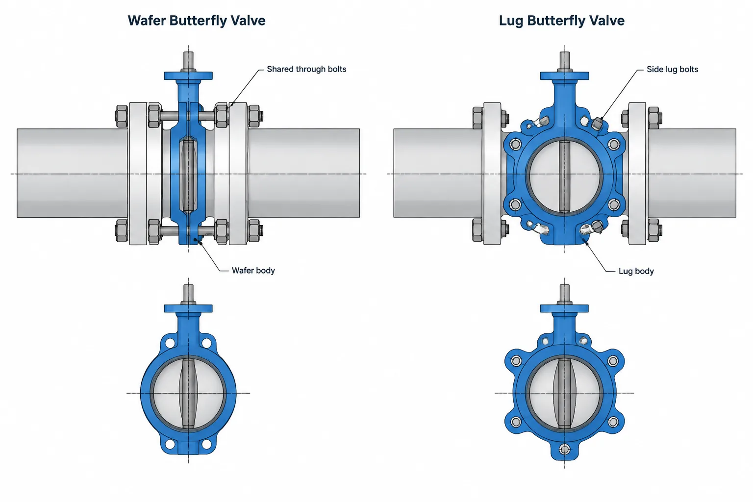
Choosing between wafer and lug butterfly valves is not simply a catalog-description decision. The body arrangement changes how adjoining flanges are fastened, how the assembly can be dismantled, and which clearances must be represented in the piping model.
This guide explains the practical differences designers and drafters should coordinate before issuing layouts, isometrics, valve lists, and material takeoffs. Final geometry, bolting, operating limits, and maintenance capability must always be confirmed from controlled project documents and verified manufacturer information.
Wafer and lug butterfly valves may perform the same basic flow-control function, but they interact with adjoining flanges and bolting in different ways. That difference affects installation, maintenance planning, piping material takeoffs, and the geometry represented in a CAD model.
The terms wafer and lug describe body and attachment arrangements. They do not, by themselves, establish the valve’s pressure capability, seat material, operating torque, shutoff performance, or suitability for a particular fluid. Those properties must be checked against the applicable piping specification, project requirements, and verified manufacturer data.
What is a wafer butterfly valve?
A wafer butterfly valve has a compact body intended to be clamped between two mating pipe flanges. Long bolts or studs generally extend across the assembly, with the exact bolting arrangement depending on the valve body, flange type, and selected product.
The valve may include centering features or a limited number of alignment holes, but the body does not normally provide a complete set of independently bolted flange connections on both sides. Tightening the joint draws the two pipe flanges together and clamps the valve body in position.
This arrangement can reduce component weight and installed length compared with some alternative valve constructions. However, the shared bolting also means that removing one adjacent flange connection can disturb the clamping system that retains the valve.
What is a lug butterfly valve?
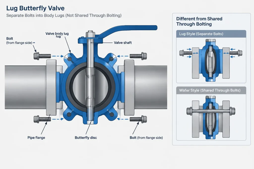
A lug butterfly valve has projections distributed around the body. These lugs provide bolt locations associated with the adjoining flanges. A common arrangement uses threaded lugs so each pipe flange can be bolted to its respective side of the valve, although actual lug and hole configurations must be confirmed from the selected product.
The separate attachment can be useful where one side of the piping may need to be disconnected while the valve remains attached to the other side. This possibility is one reason lug valves are often considered for maintenance-sensitive layouts.
However, a lug body should not automatically be assumed suitable for pressure containment with piping removed from one side. Dead-end service capability can depend on body design, seat construction, pressure direction, temperature, bolting, and manufacturer limits. The required condition must be stated and verified rather than inferred from the word lug.
Key differences for piping design
| Design issue | Wafer body | Lug body |
|---|---|---|
| Attachment concept | Clamped between mating flanges, commonly with shared through bolting | Flanges attach at body lugs, commonly from opposite sides |
| Removal of adjacent piping | Opening the shared joint may release or disturb the valve | May permit one side to be disconnected while the other remains attached, subject to product limitations |
| Bolting representation | Bolts or studs may span the valve and both flanges | Bolts commonly terminate within or at the body lugs |
| Body envelope | Typically lacks a full ring of projecting attachment lugs | Includes lugs that can increase the local radial envelope |
| Dead-end service | Must not be assumed | Must be specifically verified even when the valve has threaded lugs |
| CAD substitution | Cannot be replaced by merely changing a description | Requires the correct body, bolt pattern, and connection behavior |
Face-to-face length is not the only CAD dimension
A simplified model may represent either valve as a short cylinder between two flange faces. That can be adequate for an early routing study, but it does not capture all the geometry needed for detailed coordination.
Important valve geometry can include:
- Face-to-face or installed body length
- Body outside envelope
- Lug projection and location
- Flange-facing contact areas
- Bolt or stud paths
- Disc sweep beyond the valve body
- Stem, neck, packing, and mounting geometry
- Lever, gear operator, actuator, or accessory envelope
The face-to-face dimension controls the axial space occupied between adjoining flange reference planes. It does not prove that the valve clears the pipe bore, neighboring bolts, insulation, supports, or nearby equipment.
Check disc swing into adjoining components
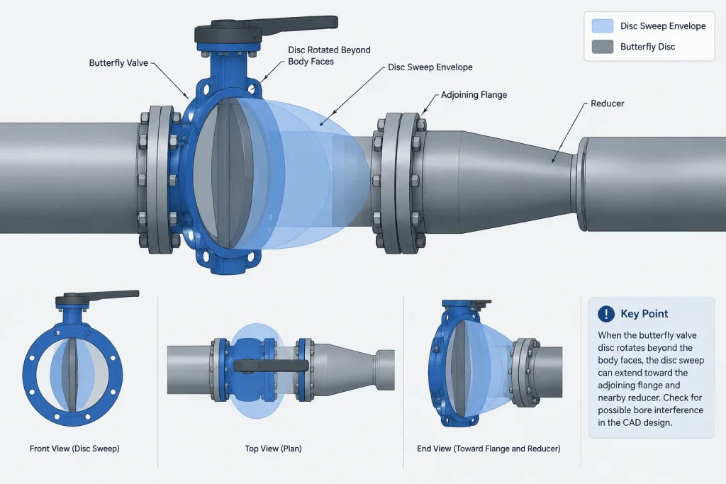
The butterfly disc rotates through the valve bore and may extend beyond the body faces while opening. An adjoining flange bore, pipe lining, reducer, check valve, or other close-coupled component can interfere with that motion even when the face-to-face stack appears correct.
A useful CAD component should therefore include either the actual disc envelope or a conservative movement envelope based on verified product information. A closed-disc symbol alone cannot demonstrate operating clearance.
Bolting must match the body arrangement
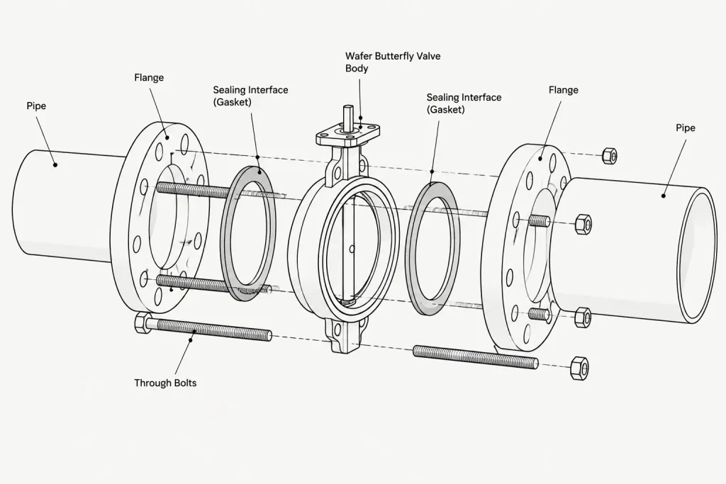
Wafer and lug valves should not share a generic bolting assembly without review. Their bolt lengths, thread engagement, insertion directions, and removal paths may differ.
For a wafer arrangement, the modeled joint stack may include both pipe flanges, gasket or sealing interfaces as applicable, the valve body, and shared bolts or studs. The installer must be able to insert, tighten, and later remove that bolting without obstruction.
For a lug arrangement, bolts may enter from each flange side and engage threaded body lugs. Excessive bolt length can cause a bolt to bottom in a blind threaded hole or conflict with a bolt approaching from the opposite side. Insufficient engagement is also unacceptable. Bolt selection should come from the approved valve and joint documentation rather than from visual estimation in CAD.
Modeling every thread is rarely necessary, but the model should preserve the correct fastening concept. The bill of materials should also distinguish through bolting from valve-specific flange bolts where the procurement system requires that distinction.
Maintenance and removal planning
Valve selection affects more than initial installation. The layout should show how the valve or adjoining spool can be removed after the plant is operating.
Questions to review include:
- Can the flange faces be separated enough to release the valve without damaging the seat?
- Is there room to withdraw long wafer-valve bolts or studs?
- Can lug-valve bolts be removed past structural steel, equipment, or insulation?
- Will the valve remain supported when adjacent piping is disconnected?
- Is the operator removable before the body is extracted?
- Does the maintenance procedure require temporary supports or restraints?
- Is one-sided pressure containment actually required during maintenance?
A lug valve may simplify a particular disassembly sequence, but it does not eliminate the need to isolate, depressurize, drain, restrain, and support the system in accordance with the approved procedure.
Common CAD and specification mistakes
Treating wafer and lug as interchangeable
Two valves with the same nominal pipe size may have different body envelopes, bolting, mass, operator geometry, and maintenance behavior. Replacing one with the other requires more than editing a component description.
Assuming every lug valve supports dead-end service
The presence of threaded lugs is not a universal dead-end rating. Verify the permitted pressure, direction, temperature, and installation arrangement for the selected valve.
Using a flange bolt set for a wafer valve without checking length
A standard flange-to-flange bolt assumption may not account for the valve body and its seating surfaces. Joint stack-up and manufacturer instructions control the required fastening arrangement.
Ignoring lug and operator envelopes
A centerline-only symbol can miss clashes between lugs, bolts, insulation, valve operators, cable trays, or structural members. Detailed coordination requires the relevant external envelope.
Placing a reducer immediately against the valve
A nearby reducer or restricted bore may interfere with the rotating disc. Close coupling should be checked with actual bore and disc geometry instead of assumed from nominal sizes.
A practical CAD workflow
- Identify the required body style. Record whether the design calls for wafer, lug, or another butterfly-valve body arrangement.
- Confirm the mating flange interfaces. Check flange type, facing, bore, gasket or seat arrangement, and material-class requirements.
- Obtain verified dimensional data. Use the approved manufacturer drawing or controlled project catalog for face-to-face length, body envelope, lugs, stem, and operator.
- Model the connection behavior. Represent shared through bolting for a wafer valve or side-specific lug bolting as applicable.
- Check the open-disc envelope. Review interference with flange bores, lining, pipe inside diameter, reducers, and nearby components.
- Review installation and removal paths. Include bolt withdrawal, flange separation, valve extraction, lifting, and temporary support needs.
- Coordinate documentation. Ensure the model, valve list, piping specification, isometric, and material takeoff identify the same body and end arrangement.
- Control substitutions. Recheck dimensions and maintenance assumptions whenever the manufacturer or body style changes.
Selection depends on the required system function
The choice between wafer and lug butterfly valves should be based on the complete installation rather than body compactness alone. A wafer valve can provide an efficient flanged-line arrangement where shared bolting and the planned maintenance sequence are acceptable. A lug valve can offer a different attachment strategy that may support easier separation of one side, but only within the verified limits of the selected design.
For CAD and piping documentation, the essential rule is to model the connection that will actually be purchased and installed. Body style, bolting, disc clearance, operator envelope, and maintenance access should remain coordinated from the piping specification through the final model and drawings.
What the CAD model should communicate
A coordinated valve model should communicate more than the location of a component on a pipe centerline. It should identify the intended body style, preserve the correct attachment concept, and provide enough external and internal clearance information for design review.
At an early layout stage, a simplified envelope may be appropriate. As the design develops, the component should be updated with verified body, disc, stem, operator, and connection geometry. The required level of detail depends on the purpose of the model, but simplification should not conceal a known interference or imply an unsupported maintenance condition.
Connection intent
The model, piping specification, valve list, and material takeoff should consistently distinguish a body clamped by shared bolting from a body attached through lugs. This distinction helps prevent purchasing errors and avoids treating unlike fastening arrangements as interchangeable.
Operating clearance
Static body clearance does not establish that the valve can operate. Design review should consider the moving disc and operator as well as the stationary body. Nearby flange bores, pipe linings, reducers, supports, insulation, equipment, and structural members may affect operation or access.
Maintenance clearance
Removal planning should consider the sequence rather than only the final empty space. Bolts must have a usable withdrawal path, flange faces may need separation, and the valve or adjoining piping may require support. An unobstructed body envelope alone does not demonstrate that disassembly is practical.
Recommended design-review handoff
Before the valve arrangement is released for detailed documentation, the responsible disciplines should agree on the body style, flange interfaces, bolting concept, operator orientation, disc-clearance basis, and expected maintenance sequence. Any assumption that depends on the selected product should remain clearly identified until verified data are incorporated.
- Piping design: Confirm routing, flange interfaces, access, support implications, and removable-spool strategy.
- Mechanical or valve engineering: Confirm the selected valve construction, service requirements, and product limitations.
- Materials or procurement: Keep body style and fastening requirements consistent with the approved specification and purchase description.
- CAD administration: Prevent unlike wafer and lug components from sharing misleading graphics, connection rules, or material codes.
- Operations and maintenance: Review isolation, access, handling, and disassembly assumptions where maintainability is important.
A CAD model is a coordination tool, not proof of pressure capability or dead-end suitability. Those conditions require explicit engineering requirements and verified product documentation.
Frequently asked questions
Can a wafer butterfly valve and a lug butterfly valve use the same CAD symbol?
A common schematic symbol may be acceptable where body construction is outside the drawing purpose. A detailed piping model should distinguish their attachment behavior, body envelope, bolting, and maintenance implications.
Does a lug butterfly valve automatically permit piping removal from one side?
No. The lug arrangement may allow separate attachment of the adjoining flanges, but the permitted maintenance and pressure condition depends on the selected valve design and verified manufacturer limits.
Why should the open disc be represented in the model?
The disc can move beyond the body faces and conflict with an adjoining bore, lining, reducer, or close-coupled component. A closed-valve representation cannot establish full operating clearance.
Is face-to-face length enough for valve layout?
No. It establishes axial placement between reference faces but does not define lug projections, bolting access, disc movement, stem height, operator clearance, or removal space.
Can a wafer valve be changed to a lug valve without rerouting the line?
It should not be assumed. The replacement may affect the body envelope, fastening arrangement, operator position, material takeoff, support conditions, and maintenance sequence. Verified product geometry and project requirements must be reviewed.
Should every bolt and thread be modeled?
Not necessarily. The level of detail should match the coordination need, but the model should preserve the correct fastening concept and enough clearance to evaluate installation and removal paths.