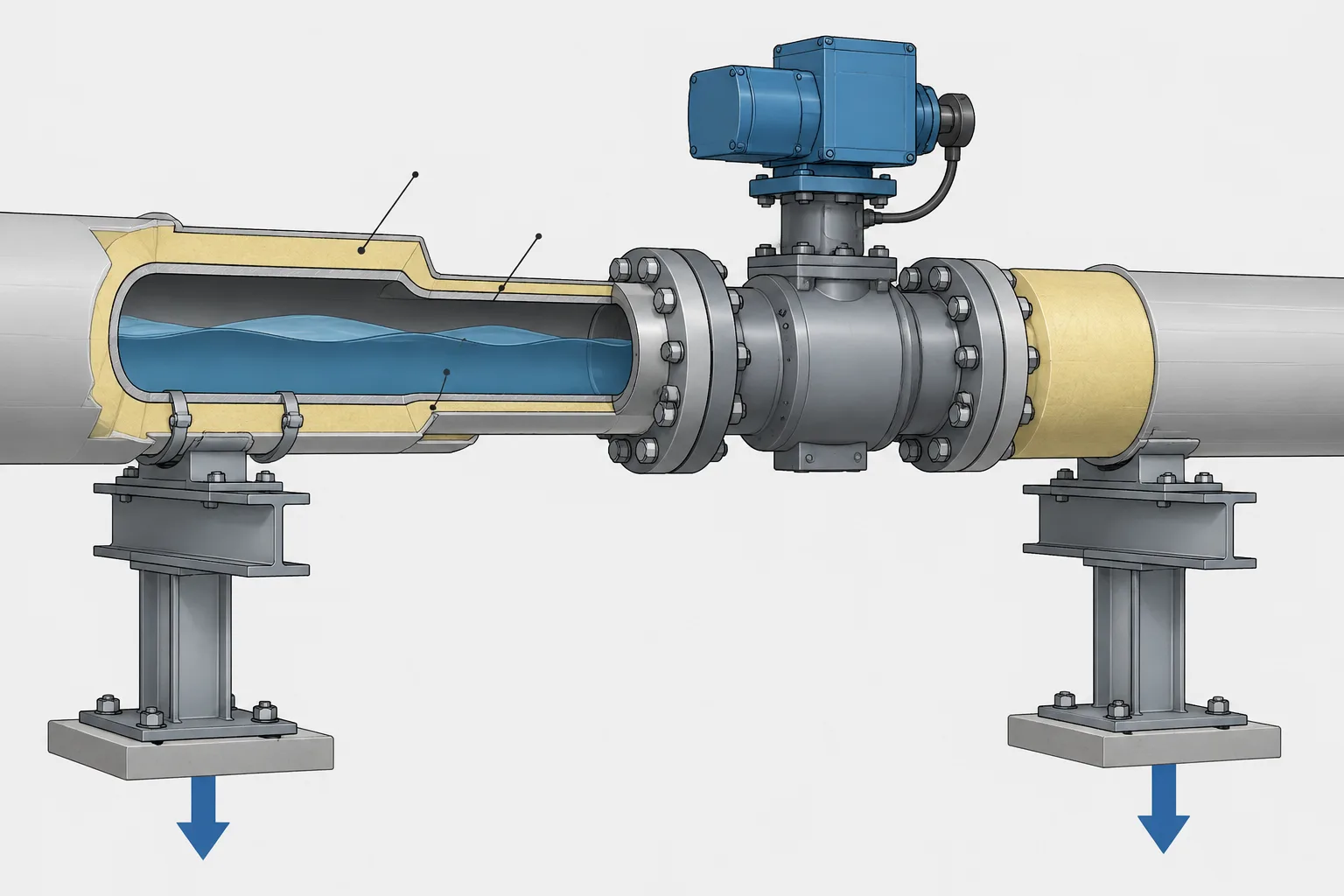
Piping weight in CAD is both a modeling issue and an engineering data-control issue. A geometrically complete model can still produce misleading load information when component mass, fluid contents, insulation, attachments, or temporary test items are missing or assigned to the wrong condition.
This reference explains how empty, operating, test, insulated, shipping, and removal cases differ. It also highlights the checks needed when CAD information is transferred to stress analysis, structural design, fabrication, lifting, construction, or maintenance workflows. Project definitions and verified source data remain essential because the same weight label may represent different inclusions in different systems.
A piping model may show every pipe run, fitting, flange, valve, and support in the correct location while still providing an incomplete picture of system weight. Geometry alone does not define the mass of the pipe wall, contained fluid, insulation, valve internals, actuators, lining, or temporary test media.
This distinction matters because different disciplines need different weight cases. A structural designer may need operating and test reactions. A piping stress analyst may evaluate several combinations of sustained, thermal, occasional, and test conditions. A fabricator may need spool weights for lifting and transportation. Plant personnel may need the removal weight of a valve or other maintainable component.
Managing piping weight in CAD therefore requires more than assigning a single value to each modeled object. The workflow must identify what the value includes, where it came from, and which load case it supports.
Mass, weight, and common unit ambiguity
Mass describes the quantity of matter in an object, while weight is the force produced by that mass under gravity. Engineering software, vendor documents, material takeoffs, and equipment schedules do not always use these terms consistently.
This can be especially confusing in U.S. customary units, where the abbreviation “lb” may appear without clearly distinguishing mass from force. Metric data may also be labeled as weight even when reported in kilograms, which are units of mass.
A project should establish how these quantities are stored and reported. Software imports and calculation transfers should not rely on a column heading alone. The unit system, quantity type, and any required conversion must be explicit.
The main piping weight conditions
There is no universal piping weight that applies to every task. The same line can have several valid weights depending on its condition.
| Weight condition | Typical contents | Common use |
|---|---|---|
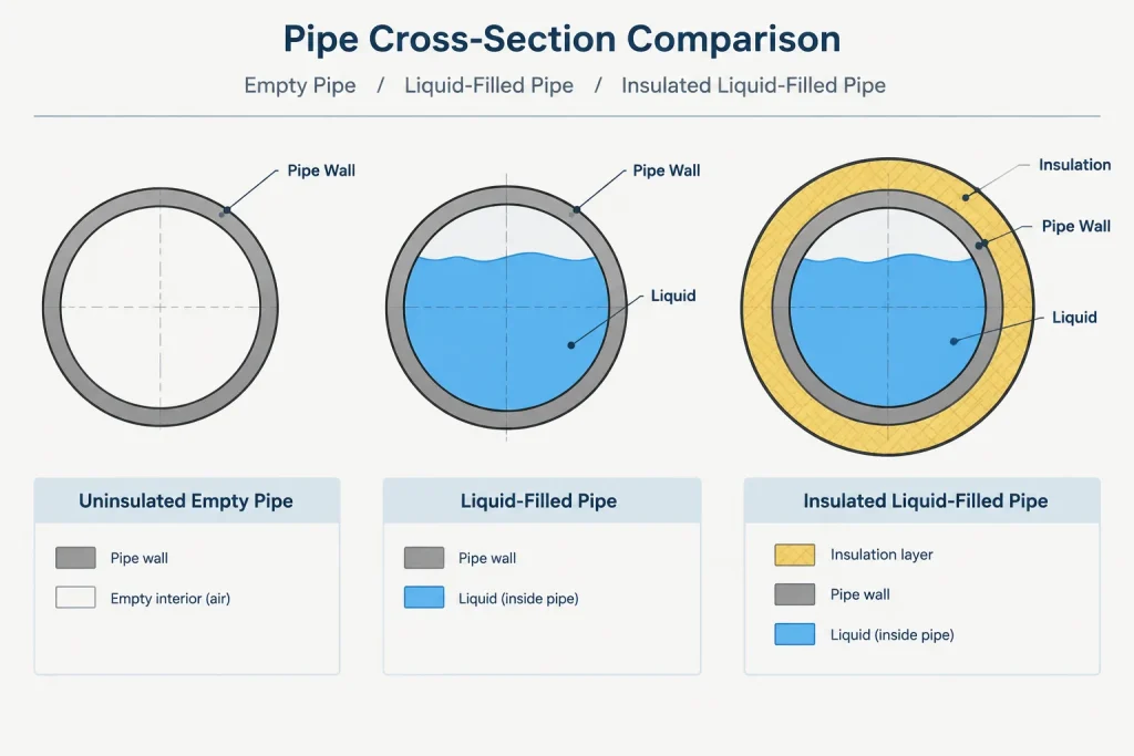
| Empty or dry | Pipe, fittings, flanges, valves, permanent attachments, and other installed hardware, without process contents | Handling, erection planning, and selected maintenance studies |
| Operating | Installed piping plus the expected process contents and applicable permanent coverings | Support, structural, and stress evaluation |
| Insulated | Dry or operating system with insulation, cladding, and relevant accessories included | Operating load assessment and support design |
| Test | Installed system filled with the specified test medium within the test boundary | Temporary support and structural load checks |
| Shipping or spool | Items included in a transportable fabrication assembly | Lifting, rigging, shipment, and shop handling |
| Removal | The component or assembly expected to be extracted during maintenance | Hoist selection, laydown planning, and access studies |
The definitions should be documented for the project. For example, an “empty” weight might include an actuator and insulation on one project but exclude them on another. A label without a scope definition can create false agreement between disciplines.
What contributes to piping system weight?
Pipe wall
Straight-pipe weight depends on the pipe outside diameter, actual modeled or specified wall basis, material density, and length. Nominal pipe size alone is not enough because different schedules or wall selections can produce different metal cross-sectional areas.
CAD systems often calculate straight-pipe length directly from the model. The associated unit weight should come from controlled reference data or a verified calculation, not from visual geometry or an unrelated catalog entry.
Process contents
The weight of liquid contents depends on the internal flow area, filled length, and fluid density for the condition being evaluated. Because inside diameter changes with wall thickness, using nominal size as the bore can distort the result.
Gas contents may be treated differently from liquid contents depending on the analysis and project procedure. Partially filled, flashing, two-phase, or solids-bearing services require an engineering basis rather than an automatic assumption that the pipe is either completely full or empty.
Fittings, flanges, and valves
Component weight is not reliably determined from its external envelope. Two valves with similar end dimensions can differ substantially because of body construction, trim, operator type, pressure class, or manufacturer design.
Generic library values may be useful during early layout, but manufacturer or supplier data should replace estimates when the selected component becomes known. Heavy operators, gearboxes, extensions, bypasses, and accessories must be included if they are part of the installed assembly.
Insulation, lining, and external coverings
Insulation weight depends on the covering system, thickness, density, cladding, and accessories. Weather barriers, removable covers, heat-tracing hardware, and accumulated moisture may also matter under the project design basis.
Internal linings and coatings can add weight while reducing the available bore. They should not be represented merely as an external CAD note if their mass affects support, handling, or structural decisions.
Attachments and specialty items
Pipe shoes, trunnions, wear pads, reinforcement, strainers, traps, inline instruments, specialty joints, and temporary test items can create concentrated loads. Small attachments may be grouped under an approved allowance, but significant items should be represented individually where their location affects reactions or center of gravity.
Why total weight is not enough
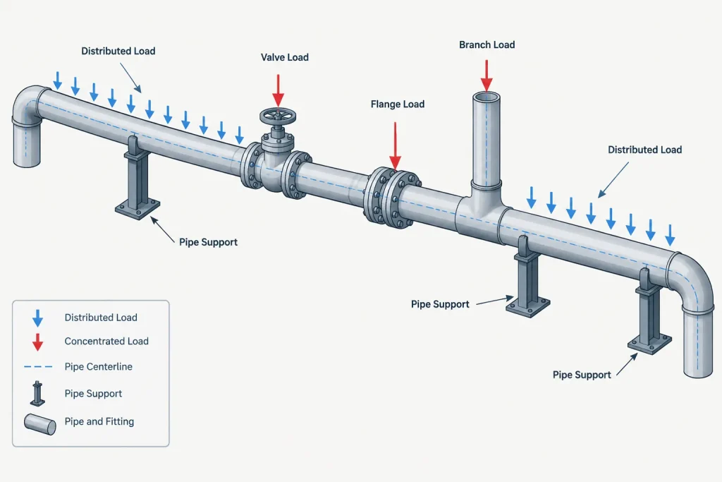
A total line weight does not describe where the load acts. Support and structural calculations depend on the distribution of weight along the route and on concentrated loads from valves, flanges, specialty components, and branches.
A simplified model may treat straight-pipe weight as a uniformly distributed load and components as point loads at defined locations. More detailed systems may derive load distribution from component geometry. In either case, the reference point must be understood. Assigning an entire valve assembly weight to the wrong port or center can alter local support reactions.
Center of gravity is particularly important for actuated valves, eccentric equipment, removable spools, and lifting assemblies. A visually centered CAD block does not prove that the real assembly is balanced about the pipe centerline.
Test weight needs separate attention
A hydrostatic or other liquid-filled test condition may be more demanding than normal operation for lines that usually carry a low-density fluid or remain partly empty. The test boundary may also include sections that do not share the same operating condition.
The test case should be based on the defined test limits, test medium, fill condition, temporary blinds or closures, and any temporary equipment. High points, low points, isolated branches, and trapped volumes can affect what is actually filled.
Temporary supports should not be assumed simply because the operating support arrangement appears adequate. Test reactions need coordination among piping, stress, structural, construction, and testing personnel using verified project criteria.
A practical CAD data workflow
- Define the load cases. Establish what empty, operating, test, insulated, shipping, and removal conditions include.
- Separate geometry from engineering data. Store weight-related properties in controlled fields rather than embedding assumptions only in graphical blocks.
- Record the data source. Identify whether a value is calculated, taken from a controlled reference, supplied by a manufacturer, or estimated for preliminary design.
- Assign a confidence status. Mark preliminary values so they can be found and replaced as purchasing information develops.
- Control units. Define whether each property is mass, force, mass per length, or force per length.
- Include accessories deliberately. Avoid both omission and double counting of actuators, insulation, shoes, tracing, and attachments.
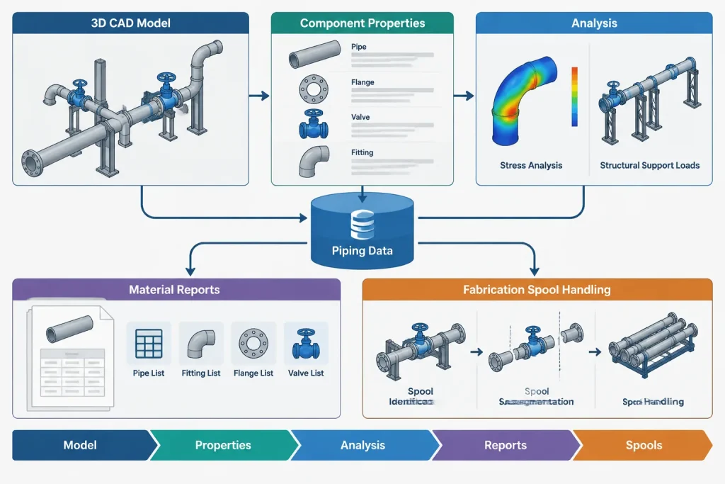
- Transfer data to analysis tools carefully. Confirm component mapping, load locations, fluid assumptions, and unit conversion after export.
- Reconcile reports. Compare CAD material quantities, stress-model weights, structural loads, and fabrication spool reports at planned project stages.
Common errors to check
- Using one weight field for every load condition.
- Calculating contents from nominal size instead of the applicable inside diameter.
- Applying straight-pipe unit weight to elbows, tees, or reducers.
- Leaving generic valve weights after manufacturer data becomes available.
- Excluding actuators, gear operators, or valve accessories.
- Counting insulation in both the component record and a separate line allowance.
- Assuming every operating line is completely liquid-filled.
- Ignoring concentrated loads near branches or unsupported valve assemblies.
- Using a model object insertion point as the center of gravity without verification.
- Reporting a precise total from data that remains preliminary.
What should appear on drawings and reports?
Not every piping drawing needs to display weight data. Adding numerous load labels to arrangement drawings or isometrics can reduce clarity and create another revision path. Weight is often managed more effectively in component properties, stress models, support load reports, spool records, lifting plans, and equipment schedules.
When weight is shown, the document should state the condition and units. A value labeled only “weight” is incomplete if the reader cannot tell whether it represents an empty component, an operating assembly, a test condition, or a shipping package.
CAD accuracy does not guarantee load accuracy
A detailed piping model can support reliable weight calculations, but only when its attributes match the physical system and the intended load case. Accurate centerlines and component envelopes do not automatically provide correct densities, bores, insulation systems, fluid conditions, accessory weights, or centers of gravity.
The best workflow treats piping weight as controlled engineering data linked to geometry. It preserves the distinction between estimated and verified values, separates permanent and temporary conditions, and communicates assumptions clearly to stress, structural, fabrication, construction, and maintenance teams.
Turning model weight into a reviewable deliverable
A useful weight report should allow another discipline to understand both the result and its basis. In addition to identifying the load condition, the report should distinguish calculated properties, controlled reference values, supplier data, and preliminary estimates. This makes unresolved information visible instead of allowing an estimated value to appear fully verified.
Projects may also assign responsibility for different parts of the weight basis. Piping design may control modeled components and routing, process engineering may define contents and operating conditions, insulation specialists may define covering systems, suppliers may provide assembly data, and stress or structural teams may determine how loads are applied. The responsibility split should be documented rather than assumed.
Use an exception-based review
Reviewing only the final total can hide errors that offset one another. An exception report is often more useful because it identifies objects with missing weight properties, generic values, uncertain centers of gravity, duplicate allowances, or conflicting units.
- Missing-data exceptions: Components or line segments with no applicable property for the selected condition.
- Preliminary-data exceptions: Values that still depend on a generic library or engineering allowance.
- Scope exceptions: Items whose inclusion differs between the CAD, stress, structural, or fabrication model.
- Location exceptions: Concentrated loads assigned to an insertion point that has not been confirmed as the load application point.
- Revision exceptions: Weight data that has not been reconsidered after a component, wall basis, covering system, fluid basis, or test boundary changed.
Reconcile by scope before comparing totals
Two reports should not be expected to agree until their boundaries and inclusions agree. A CAD material report may represent installed items, while a stress model may include analytical allowances and a fabrication report may include only a defined spool. The comparison should first align line limits, components, attachments, contents, insulation, temporary items, and quantity type.
Differences should be resolved at the component or segment level where practical. This helps distinguish a real data error from a legitimate difference in analytical purpose.
Questions for a model-weight review
- Is the reported quantity mass, force, or a distributed value?
- Which physical items are included in the selected condition?
- Are fluid contents based on the applicable bore and fill assumption?
- Are valves and specialty items still using generic library data?
- Are actuators, operators, supports, linings, and coverings included exactly once?
- Do concentrated loads act at verified locations?
- Does the test case follow the actual test boundary and temporary configuration?
- Can preliminary values be identified and replaced without searching the entire model?
- Have exported properties and units been checked in the receiving analysis system?
These questions do not replace project calculations. They provide a practical audit trail so that model-derived weight can be reviewed, revised, and communicated without relying on geometry alone.
Frequently Asked Questions
Can a CAD model calculate operating piping weight automatically?
It can support the calculation when the model contains controlled component properties, the applicable bore basis, fluid information, covering data, and clear load-case rules. Automation does not make missing or generic inputs accurate.
Are empty weight and insulated weight separate conditions?
That depends on the project definition. Insulation may be treated as an addition to an empty or operating condition rather than as a completely independent case. Reports should state whether insulation, cladding, tracing accessories, and removable covers are included.
How should unknown valve or actuator weights be managed?
A preliminary value may be used when permitted by the project workflow, but it should be marked as estimated and linked to its basis. The record should also have a clear trigger for replacement when supplier information becomes available.
Why can CAD and stress-model weight reports disagree?
Common causes include different model boundaries, units, component mappings, fluid assumptions, insulation treatment, analytical allowances, and load locations. The reports should be reconciled by scope and component before their totals are compared.
Does a detailed component model provide its true center of gravity?
Not necessarily. A graphical origin or geometric center may differ from the center of gravity of the manufactured assembly, particularly when an actuator, gearbox, extension, or other offset accessory is present. Verified supplier information may be required.
When should piping weight data be reviewed again?
Review is appropriate after changes to routing, wall selection, material, component type, valve operator, insulation, lining, fluid basis, test boundary, attachments, or fabrication limits. The project workflow should identify which changes trigger recalculation and cross-discipline notification.