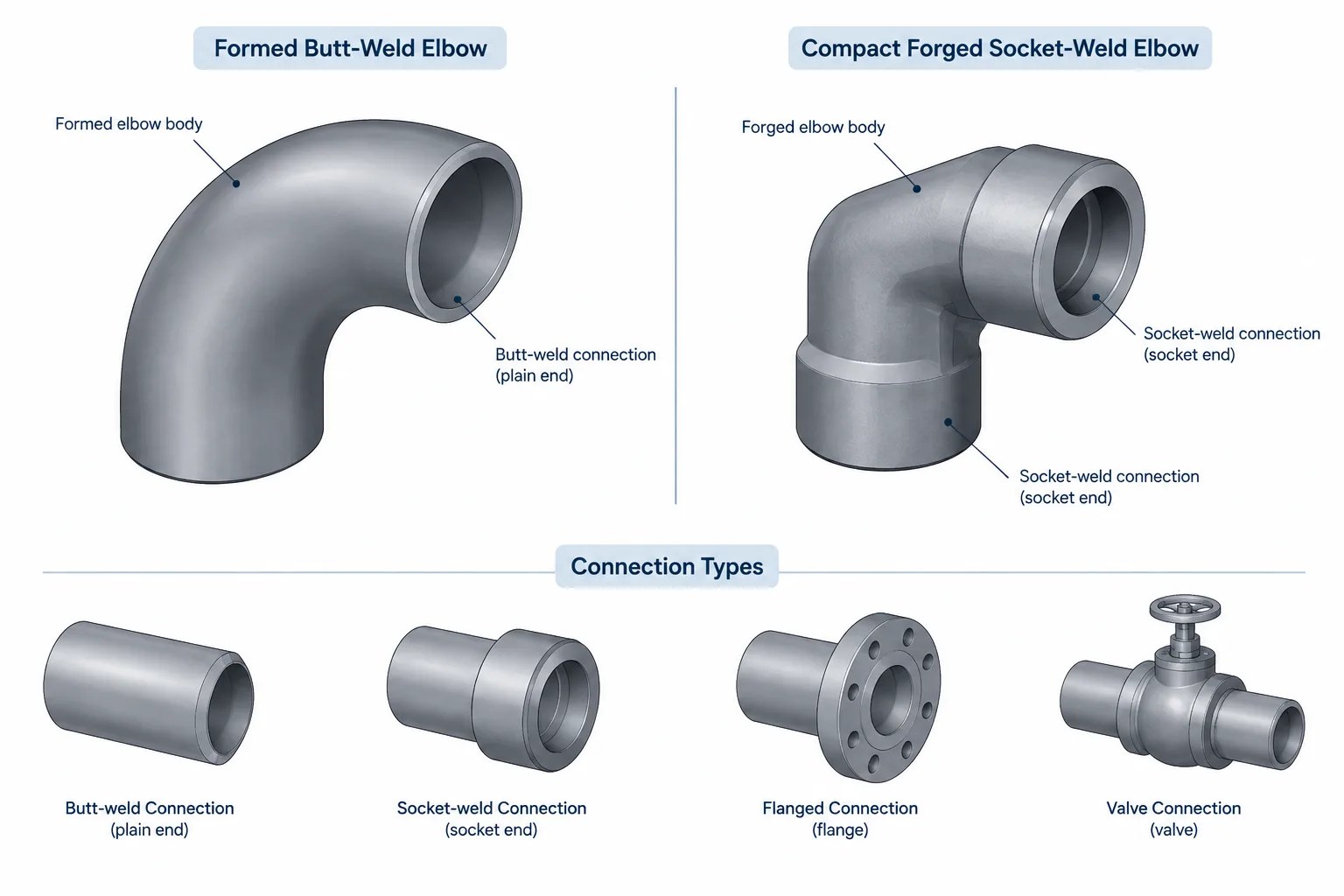
Wrought vs. forged pipe fittings is not simply a comparison of strength or quality. In practical piping documentation, the terms help identify different product families that commonly use different connections, designation methods, dimensional references, and CAD rules.
This guide explains how to distinguish these fitting categories when reviewing piping specifications, selecting components, building CAD libraries, checking model connectivity, and preparing bills of materials. The objective is to describe each fitting completely rather than relying on its appearance or manufacturing label alone.
The terms wrought fitting and forged fitting are often treated as descriptions of strength or quality. In piping work, however, they primarily identify manufacturing and product categories. They also tend to correspond with different fitting standards, end connections, dimensional conventions, and specification practices.
This distinction matters when selecting components, building a piping specification, creating CAD content, or checking an isometric bill of materials. A generic fitting shape is not enough. An elbow intended for butt welding is not interchangeable with a socket-weld elbow merely because both have the same nominal size and angle.
What Does “Wrought” Mean for Pipe Fittings?
In metallurgy, wrought generally describes metal that has been mechanically worked rather than produced as a final cast shape. For common piping applications, the term is strongly associated with factory-made butt-welding fittings such as elbows, tees, reducers, returns, and caps.
These products may be manufactured using forming, pressing, extrusion, drawing, or other controlled processes appropriate to the fitting type and material. The exact production route can vary. Therefore, “wrought” should not be interpreted as one single manufacturing method.
ASME B16.9 is commonly associated with factory-made wrought butt-welding fittings. Project specifications may also reference material specifications, dimensional requirements, examination requirements, and additional purchaser restrictions. The fitting’s complete identity comes from this combination, not from the word “wrought” alone.
Typical characteristics of the wrought fitting category
- Commonly supplied with butt-weld ends.
- Includes elbows, tees, reducers, caps, crosses, and returns.
- Usually selected by nominal pipe size and a wall designation or compatible end thickness.
- Installed as part of a continuous welded piping system.
- Represented in CAD using center-to-end, end-to-end, and fitting-envelope dimensions from the applicable dimensional reference.
Butt-weld fittings are often described by schedule, nominal wall thickness, or an associated pipe wall designation. Designers must still verify the specified fitting wall, end preparation, and bore transition. A schedule label by itself does not resolve every detail at the weld joint.
What Does “Forged” Mean for Pipe Fittings?
Forging shapes metal through localized compressive working, usually before final machining. In common piping terminology, forged fittings usually refers to compact socket-weld and threaded fittings such as elbows, tees, couplings, crosses, plugs, bushings, and unions.
ASME B16.11 is commonly associated with forged socket-welding and threaded fittings. These products are generally designated using a fitting class rather than a pipe schedule as the primary product class. The connected pipe still has its own size and wall designation, so the fitting class and pipe schedule must not be stored as though they were the same property.
Typical characteristics of the forged fitting category
- Commonly supplied with socket-weld or threaded ends.
- Often used in smaller-bore branch, utility, drain, vent, and instrument-related piping.
- Selected using nominal size, end type, fitting class, material, and specification requirements.
- Frequently has a compact, block-like external envelope compared with a formed butt-weld fitting.
- Requires connection-specific modeling rules for sockets or threads.
The word “forged” does not mean that every forged product is automatically suitable for severe service. Suitability depends on the complete piping design basis, including material, class, end connection, service conditions, code requirements, and project specification.
Wrought and Forged Fittings Compared
| Topic | Wrought fitting category | Forged fitting category |
|---|---|---|
| Common connection | Butt weld | Socket weld or threaded |
| Common fitting forms | Elbows, tees, reducers, caps, crosses, returns | Elbows, tees, couplings, unions, plugs, bushings, crosses |
| Typical designation approach | Nominal size with wall or schedule-related information | Nominal size with fitting class and end type |
| CAD connection point | Usually located at the weld-end plane | Usually defined at the socket or threaded connection interface |
| Cut-length concern | Fitting takeout between weld-end planes | Socket insertion or threaded makeup affects connected pipe length |
| Common documentation risk | Incorrect wall, end preparation, or reducer size order | Missing class, mixed end type, or incorrect insertion assumption |
This comparison describes common industry usage rather than a universal rule for every component. Some products and specialized specifications do not fit neatly into these simplified categories. Always classify a fitting from its governing product description and approved piping specification.
Why Manufacturing Terminology Is Not Enough for Selection
A bill of materials entry such as “forged elbow” is incomplete. It does not establish whether the component is threaded or socket welded, what its fitting class is, which material is required, or what nominal size applies. Likewise, “wrought reducer” does not identify whether the reducer is concentric or eccentric, its large and small ends, or the required wall.
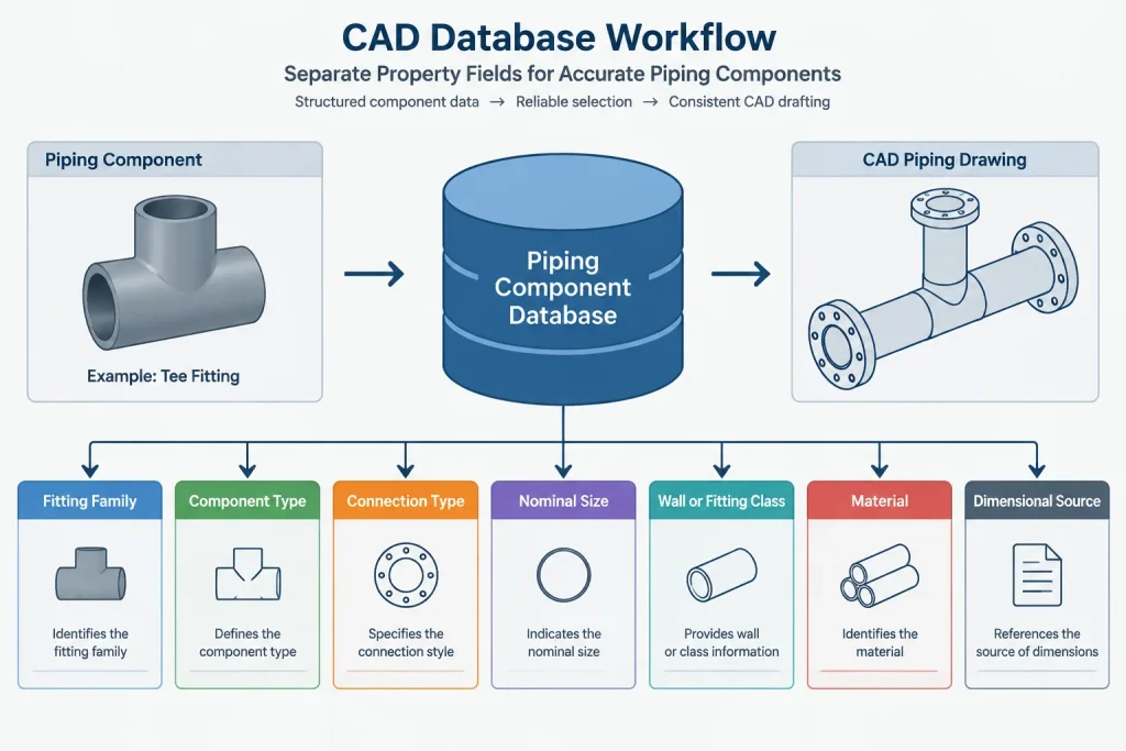
A useful fitting description should communicate the properties needed to select the intended catalog family. Depending on the component, these may include:
- Fitting type and geometry.
- Nominal size or ordered size sequence.
- End connection at each port.
- Wall designation or fitting class, as applicable.
- Material specification and grade.
- Required product or dimensional standard.
- Special bore, branch, corrosion, or project requirements.
Do not infer material from manufacturing terminology. Carbon steel, stainless steel, alloy steel, and other material families may all contain products described as wrought or forged. Material must remain an explicit controlled property.
CAD Modeling Differences
Butt-weld fitting ports
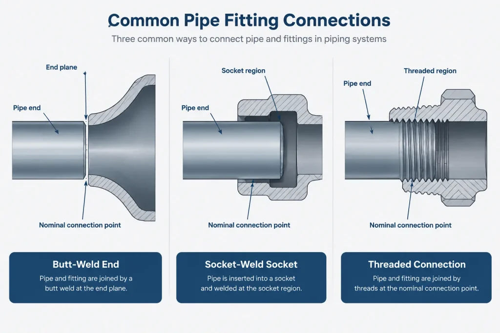
A butt-weld fitting port is normally modeled at the fitting end plane on the pipe centerline. The fitting takeout controls the distance from that end plane to another port, a center intersection, or a tangent reference, depending on the component.
The model should also carry the end size and compatible wall information. A visually connected centerline does not prove that the fitting bore, outside diameter, or weld-end thickness matches the adjoining pipe.
Socket-weld fitting ports
A socket-weld fitting contains an internal socket that receives the pipe end. CAD libraries need a consistent distinction between the fitting face, socket bottom, intended pipe-end location, and reported connection point. If the insertion convention is unclear, modeled pipe cut lengths may not agree with fabrication practice.
Highly simplified models do not need to show every internal surface, but the underlying port data should preserve the assembly logic. The project’s fabrication requirements determine how any assembly gap is controlled and documented.
Threaded fitting ports
Threaded connections introduce makeup rather than a simple face-to-face contact. Actual engagement can be affected by thread form, tolerances, sealant, component geometry, and assembly practice. A CAD model commonly uses a nominal connection location, but that point should not be misrepresented as a guaranteed field makeup position.
For this reason, threaded assemblies should not be dimensioned by measuring arbitrary solid-model intersections. Use the project’s approved component data and drafting convention.
How to Structure a Fitting Library
A reliable CAD or database library should separate properties that are frequently confused. Recommended fields include:
- Manufacturing or product family: wrought, forged, cast, fabricated, or another defined category.
- Connection type: butt weld, socket weld, threaded, flanged, grooved, or other.
- Component type: elbow, tee, reducer, coupling, cap, plug, or union.
- Size fields: one field for each ordered port, using a consistent sequence.
- Rating field: wall designation, fitting class, flange class, or another product-appropriate value.
- Material fields: material specification and grade stored separately from geometry.
- Dimensional source: the verified standard or manufacturer data used to create the geometry.
Avoid one generic “rating” field that mixes pipe schedule, forged fitting class, and flange pressure class. These designations come from different product systems and are not interchangeable.
Drawing and BOM Review Checklist
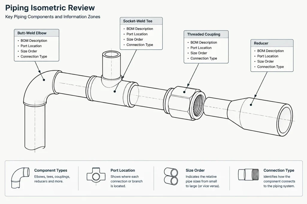
When checking fittings on an isometric, model, or material takeoff, review the following:
- Does the fitting family match the specified connection type?
- Are socket-weld and threaded components clearly distinguished?
- Is fitting class stored separately from connected pipe schedule?
- Are butt-weld fitting wall and end compatibility verified?
- Are reducing sizes listed in the correct order?
- Does the model use the correct port and insertion convention?
- Is the material specification explicit rather than inferred?
- Are special or mixed-end fittings identified without relying on appearance?
- Does the bill of materials describe the component completely enough for purchasing review?
Practical Takeaway
Wrought and forged are useful piping terms, but neither term completely defines a fitting. In common practice, wrought fittings are closely associated with butt-weld systems, while forged fittings are closely associated with socket-weld and threaded systems. The decisive selection information still includes size, connection, wall or class, material, geometry, and the governing project specification.
For CAD work, the most important lesson is to model the connection system rather than only the visible fitting shape. Correct ports, takeouts, insertion assumptions, and property fields allow drawings and bills of materials to remain consistent from design through fabrication and installation.
Applying the Distinction in a Design Workflow
Start with the approved piping specification rather than the shape shown in a catalog or CAD model. Confirm the component type, ordered size sequence, connection at each port, material, and the product-appropriate wall or class designation. The manufacturing or product-family term should support these properties, not replace them.
Next, verify that the CAD component uses connection logic appropriate to the selected fitting. Butt-weld components depend on controlled end planes and fitting takeout. Socket-weld components require a defined relationship among the fitting face, socket, and pipe-end location. Threaded components require a documented nominal makeup convention rather than an arbitrary solid-model intersection.
Finally, compare the model properties with the drawing callout and bill of materials. If the model says only “elbow” or “tee,” the data is usually too broad for dependable material reporting. A reviewer should be able to determine the intended fitting family and connection without interpreting geometry by eye.
Common Classification Errors to Avoid
- Treating wrought as a material grade: The material specification and grade must remain separate controlled properties.
- Treating forged as a service rating: The manufacturing term alone does not establish suitability for the design conditions.
- Equating fitting class with pipe schedule: They belong to different designation systems and should occupy separate database fields.
- Using one port convention for every connection: Butt-weld, socket-weld, and threaded ends affect placement and pipe-length calculations differently.
- Selecting from appearance alone: Simplified CAD solids can conceal sockets, threads, bore transitions, and mixed-end configurations.
- Leaving reducing-port order undefined: Size fields must follow the project’s established ordering convention so drawings and material reports agree.
Information That Should Travel Together
A fitting record is most useful when geometry, connection data, specification data, and material data remain associated through modeling, drawing production, and purchasing review. Separating these properties into clear fields makes validation easier and reduces the chance that a visually correct component will generate an incomplete or misleading material description.
Project specifications, governing codes, approved manufacturer information, and fabrication requirements remain controlling. Generic CAD geometry and educational comparisons should be treated as reference aids rather than substitutes for project-specific verification.
Frequently Asked Questions
Are wrought fittings always butt-weld fittings?
Wrought fittings are commonly associated with factory-made butt-welding products in piping practice, but the complete product description and governing specification should control classification. The word “wrought” by itself does not fully define every end connection or dimensional requirement.
Are forged fittings always socket welded?
No. The forged fitting category commonly includes both socket-weld and threaded products. The end type must be stated explicitly in the specification, CAD record, and bill of materials.
Does forged mean stronger than wrought?
That conclusion should not be made from terminology alone. Suitability depends on the complete component definition and design basis, including material, connection, fitting class or wall designation, service conditions, and project requirements.
Can fitting class and pipe schedule use the same CAD field?
They should be stored separately. Fitting class and pipe schedule describe different product systems, even when a component and its connected pipe appear in the same assembly.
Why does the connection type matter to pipe cut length?
Each connection system locates the pipe end differently. Butt-weld layouts use fitting end planes and takeout, socket-weld layouts depend on the documented insertion convention, and threaded layouts use an assumed makeup convention. Applying the wrong port logic can produce incorrect cut-length information.
What should be checked before placing a fitting in a CAD model?
Confirm the fitting type, port sizes, size order, end connection, wall or class designation, material, dimensional source, and project-specific connection convention. Then verify that the resulting material description contains enough information for an independent review.