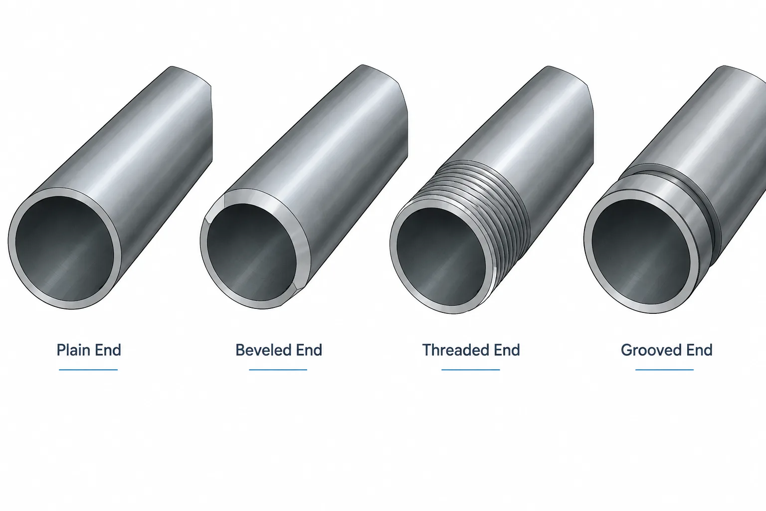
Pipe end types in CAD must be treated as design data, not merely as graphics. Plain, beveled, threaded, and grooved ends can require different mating components, fabrication operations, dimensional assumptions, and drawing notes even when the pipe itself appears identical in a general arrangement.
This reference explains how to distinguish physical end preparation from connection type, choose an appropriate level of model detail, and prevent simplified geometry from becoming an unsupported fabrication instruction. It is intended to help piping designers, CAD users, reviewers, and material-control teams maintain consistent information from the model through drawings and reports.
A pipe end is more than the point where a modeled centerline stops. Its preparation determines how the pipe can connect, what fabrication work is required, and which dimensions control the finished assembly. Two pipe pieces with the same nominal size, schedule, material, and overall length may not be interchangeable if their end types differ.
Common pipe end types include plain, beveled, threaded, and grooved ends. Socket-weld preparation and proprietary mechanical connection profiles may also appear, but they require additional assembly information. A reliable piping drawing should identify the intended joint without trying to represent every small manufacturing feature at every drawing scale.
End preparation and joint type are related but not identical
End preparation describes the physical condition of the pipe end. Joint type describes how that end connects to another component. For example, a beveled pipe end may be part of a butt-weld joint, but the complete joint also depends on the adjoining end, alignment, assembly spacing, weld procedure, and applicable project requirements.
This distinction matters in CAD and material control. A model may classify a connection as welded while omitting the bevel geometry. That can be appropriate for layout, but the fabrication documentation must still communicate the required preparation. Conversely, drawing a bevel does not by itself define the complete weld.
Common pipe end types
Plain end
A plain end is cut without threads or a prepared butt-welding bevel. Depending on the application, it may be square-cut or otherwise finished for a particular joining process. Plain-end pipe can be used with mechanical couplings, certain compression-style systems, slip-on components, or as stock that will receive additional preparation later.
The term should not be interpreted as meaning that the end requires no inspection or finishing. Cut squareness, burr removal, cleanliness, and dimensional condition can still affect assembly. A plain end intended for shop beveling is also different from a finished end ready for a mechanical coupling.
Beveled end
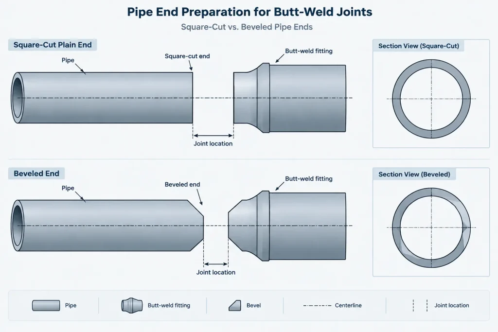
A beveled end has material removed around the edge to support a butt-weld joint. The visible bevel is only part of the weld preparation. Root-face condition, internal alignment, assembly spacing, wall-thickness transition, and the adjoining component all influence the final joint.
Detailed bevel geometry is often unnecessary in a general arrangement or coordination model. It becomes more important in fabrication details, automated cutting information, special wall transitions, and locations where bore mismatch must be evaluated. Designers should obtain the required preparation from the governing specification, fabrication procedure, and approved component data rather than scaling a generic CAD symbol.
Threaded end
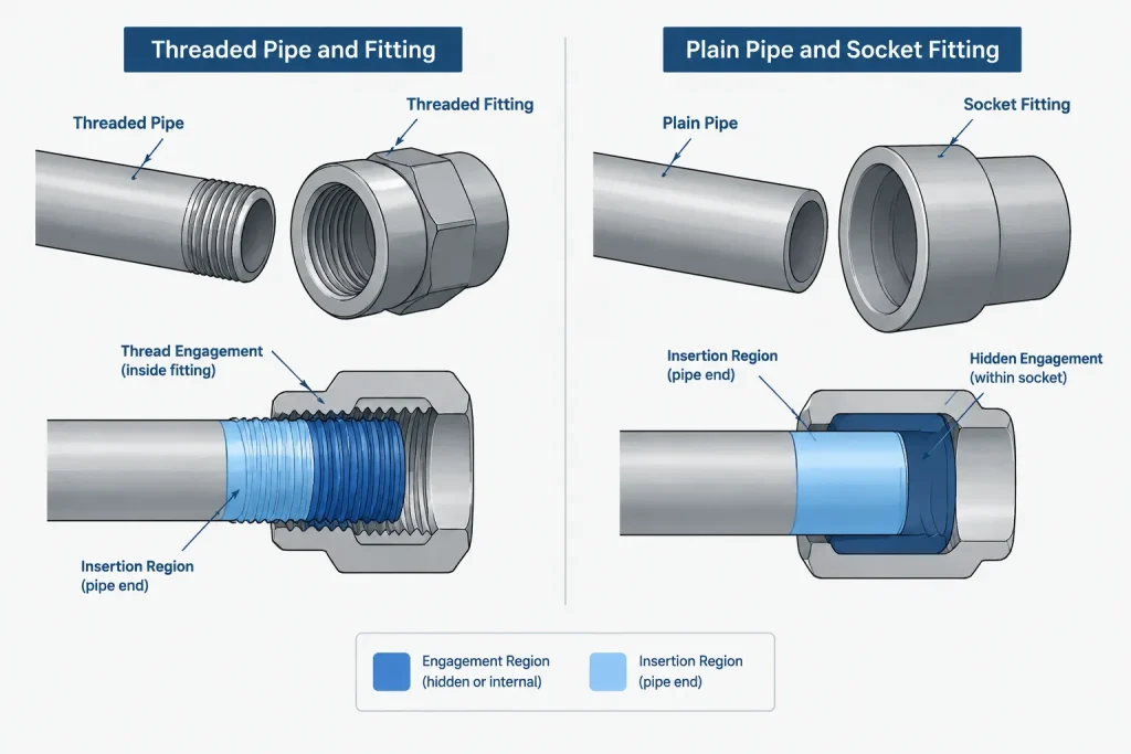
A threaded end is machined or formed to engage a compatible threaded fitting, valve, flange, or other component. The pipe does not simply stop at the visible face of the mating item. Part of it enters the connection, and the final made-up position depends on the thread form, component geometry, manufacturing variation, and assembly practice.
This makes threaded piping especially vulnerable to false cut lengths derived from simplified CAD graphics. A model may show nominal engagement for coordination, but that representation should not be treated automatically as a machining instruction. Thread type and compatibility also need to be stated in controlled project documentation; a generic note such as “threaded” may be insufficient where more than one thread system is in use.
Grooved end
A grooved end includes a formed or machined profile near the pipe end for use with a compatible mechanical coupling. The connection depends on more than the visible groove. The complete assembly includes the pipe-end condition, coupling housing, sealing element, mating component, and installation requirements.
Grooved systems may require control of the distance from the pipe end to the groove, end condition, outside-diameter compatibility, and spacing between mating ends. These details are usually better managed through verified manufacturer or project data than through an assumed generic groove profile.
Socket-weld preparation
Pipe entering a socket-weld fitting is commonly supplied with a plain cut end rather than a butt-welding bevel. The connection nevertheless requires controlled insertion into the fitting socket and an assembly condition appropriate to the governing procedure. The socket depth affects the pipe cut length even when the fitting is represented by simple centerline geometry.
For material descriptions, it is useful to distinguish the pipe’s physical end condition from the socket-weld connection type. Calling the pipe end “socket weld” without identifying the mating component can obscure what fabrication is actually required.
Comparison of documentation concerns
| End type | Typical connection context | Main CAD or drawing concern | Information to verify |
|---|---|---|---|
| Plain | Mechanical connection, slip-on assembly, or later preparation | Do not assume that a raw cut end is installation-ready | Cut finish, squareness, outside-diameter condition, and required secondary work |
| Beveled | Butt-weld joint | Separate nominal component length from weld-preparation detail | Bevel configuration, wall transition, alignment, and welding requirements |
| Threaded | Threaded fitting, valve, or flange | Account for engagement without treating a schematic model as a machining guide | Thread system, end designation, mating compatibility, and makeup assumptions |
| Grooved | Mechanical coupling system | Model the assembly envelope and preserve manufacturer-dependent geometry | Groove profile, end spacing, coupling data, and pipe compatibility |
| Plain for socket insertion | Socket-weld fitting or valve | Include socket insertion in cut-length logic | Socket depth, assembly condition, and fabrication procedure |
How pipe end type affects dimensions
End type can change the relationship between a centerline dimension, pipe cut length, and installed assembly length. The drawing team should determine which physical points a dimension controls before extracting fabrication values.
- Butt-welded pipe: Cut length may be developed between theoretical joint locations, with end preparation and assembly requirements applied through the fabrication workflow.
- Threaded pipe: The pipe extends into mating components, so visible face-to-face distance is not the same as pipe cut length.
- Socket-connected pipe: Insertion into each socket must be included when developing the pipe piece.
- Grooved pipe: End-to-end position, groove location, and the intended coupling assembly must be coordinated.
- Plain-end stock: Extra material may be required if beveling, threading, or other end processing will occur after the initial cut.
These relationships should be encoded in verified catalog data or fabrication rules where possible. Manually offsetting pipe endpoints until a drawing “looks right” creates geometry that is difficult to audit and reuse.
Choosing the right CAD representation
The appropriate amount of end detail depends on the model’s purpose. A process diagram generally needs only the connection concept. A plant layout model needs accurate component envelopes, ports, and replacement lengths. A fabrication model may need end-preparation and insertion information that would be excessive in a general arrangement.
A practical representation strategy is:
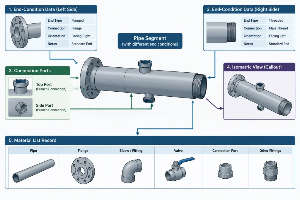
- Use centerlines and intelligent connection ports for routing.
- Store end type as component or pipe-segment data rather than relying only on visible geometry.
- Show simplified joint graphics on isometrics where they improve interpretation.
- Add enlarged details for unusual transitions, special preparations, or ambiguous connections.
- Reserve fully modeled threads, bevels, and grooves for workflows that genuinely use that geometry.
Overmodeling can make files heavy while still failing to communicate the controlling requirement. A small symbolic bevel copied across a model, for example, has little value if the material list and fabrication notes do not identify the correct end preparation.
Material descriptions and abbreviations
End-condition abbreviations often appear in purchase descriptions, bills of material, line-class data, and fabrication reports. Their meaning can vary by company, software library, manufacturer, or product family. Common shorthand may refer to beveled, plain, or threaded ends, but the abbreviation alone should not be treated as a universal specification.
Use a project legend or controlled property list, and keep separate fields where practical for:
- Pipe end preparation at each end
- Connection type at each end
- Mating component or port type
- Shop or field preparation responsibility
- Special inspection or finishing notes
Separate end fields are particularly useful for pieces with unlike ends, such as a fabricated nipple or adapter prepared differently at each side.
A review workflow for pipe ends
- Read the line and material requirements. Confirm the intended joining method before selecting components.
- Check both sides of every connection. Compatible nominal sizes do not guarantee compatible end preparations.
- Verify component ports. Make sure valve, fitting, flange, and equipment-nozzle end types match the connected pipe.
- Review cut-length logic. Identify threaded engagement, socket insertion, coupling spacing, and weld-joint locations.
- Inspect transitions. Look for changes between welded, threaded, grooved, flanged, and other connection systems.
- Confirm deliverables. Ensure isometrics, spool drawings, and material reports carry the information needed by purchasing and fabrication.
- Resolve generic placeholders. Replace preliminary components with verified project items before issuing fabrication documents.
Common mistakes to avoid
- Using “welded end” when a specific end preparation or connection description is required.
- Assuming every butt-weld component has identical end geometry.
- Calculating threaded pipe length from visible fitting faces.
- Modeling a groove but omitting the coupling envelope and access needed for assembly.
- Treating a plain end as automatically suitable for any mechanical connection.
- Allowing a component’s graphics and its stored connection data to disagree.
- Using a generic library part as evidence of project acceptance or dimensional suitability.
Key takeaway
Pipe end type is a small data field with a large effect on compatibility, fabrication, and cut-length control. CAD geometry should support that information, not replace it. By separating physical end preparation from joint type, checking both sides of each connection, and using verified project data for engagement and preparation details, piping teams can produce models and drawings that are clearer and safer to fabricate.
Managing pipe end information across deliverables
A dependable workflow carries the pipe-end requirement through several layers of documentation. The model contains the connection and end-condition properties, the drawing communicates the intended assembly, the material description supports purchasing, and the fabrication document provides the preparation information needed for the work. A correct symbol in only one of these locations does not resolve conflicting data elsewhere.
Where the CAD system permits it, end preparation and connection type should be stored as separate properties. This allows a plain end entering a socket, a beveled end used in a butt-weld joint, and a plain end awaiting later shop preparation to remain distinguishable even if their simplified graphics look similar.
Useful model checks
- Port compatibility: Compare the stored connection properties on both sides of every modeled joint.
- End-specific data: Confirm that pipe pieces with unlike ends are not described by a single ambiguous property.
- Geometry consistency: Check that visible symbols, component ports, and stored metadata describe the same connection concept.
- Length logic: Verify that engagement, insertion, joint location, and secondary end processing are handled by approved project rules rather than visual offsets.
- Document consistency: Compare the model, isometric, spool information, and material report before fabrication release.
- Placeholder control: Identify generic components whose connection data still require confirmation.
Geometry, notation, and fabrication instructions
These forms of information serve different purposes. Geometry supports routing, interference review, and assembly-envelope coordination. Drawing notation identifies the intended connection or directs the reader to controlled requirements. Fabrication instructions define the actual preparation and workmanship needed to produce the pipe piece.
Keeping those purposes separate helps prevent a schematic thread, bevel, or groove from being interpreted as verified manufacturing geometry. When detailed preparation is required, it should come from the applicable project specification, approved procedure, or verified component information rather than from scaling a symbol or generic library object.
Frequently asked questions about pipe end types
Is a beveled end the same as a butt-weld joint?
No. A bevel is a physical end preparation, while a butt-weld joint is the complete connection between adjoining components. The finished joint also depends on alignment, the mating end, assembly conditions, and the applicable welding requirements.
Can pipe end type be determined from CAD geometry alone?
Not reliably. Many layout models simplify or omit threads, bevels, grooves, and socket insertion. Connection properties, project notes, material descriptions, and approved component data should be reviewed with the geometry.
Why can threaded pipe cut length differ from the visible distance between fittings?
A threaded pipe end enters the mating component. The visible spacing between component faces therefore does not directly represent the required pipe cut length. The applicable thread and assembly information must control the result.
Should grooves and threads always be modeled in detail?
No. Detailed geometry is appropriate only when the workflow uses it for fabrication, coordination, or another defined purpose. Simplified graphics and intelligent connection data are generally more useful for routing and general documentation.
Is a plain end automatically ready for a mechanical coupling?
No. Plain end describes the absence of threads or a prepared butt-welding bevel, but the intended connection may still require a controlled cut, surface condition, outside-diameter compatibility, finishing, or another preparation.
How should a pipe piece with different preparations at opposite ends be documented?
Record the preparation and connection information separately for each end. This avoids an ambiguous overall description and helps the model, material report, and fabrication documents remain consistent.