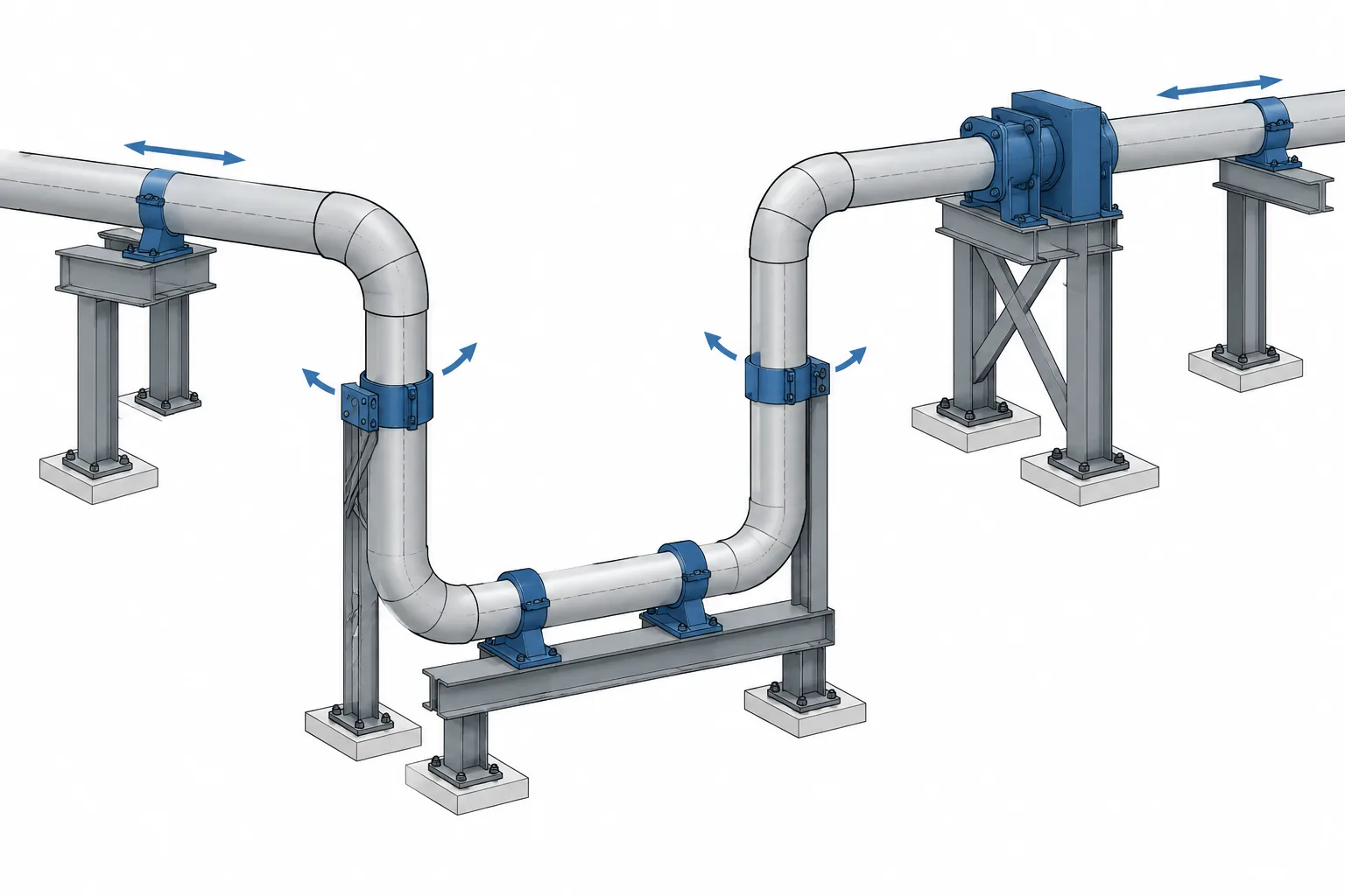
Piping expansion loops in CAD must represent both a physical route and an intended movement strategy. The visible arrangement of pipe and elbows establishes the geometry, while anchors, guides, stops, supports, clearances, and connected systems determine how that geometry can respond to temperature-related movement.
This guide explains how to document expansion-loop geometry without confusing a coordinated CAD layout with a completed flexibility evaluation. It also highlights the information needed to keep piping models, support details, isometrics, layout drawings, and engineering assumptions aligned through design revisions.
A piping expansion loop is a deliberate routing feature that adds flexibility to a pipeline. Instead of forcing thermal growth into equipment nozzles, terminal points, or rigid supports, the loop allows selected pipe legs to bend as the system expands or contracts.
In CAD, an expansion loop may look like a simple group of elbows and straight pipe. Its engineering function, however, depends on more than its visible shape. Leg lengths, elbow geometry, support conditions, connected equipment, pipe properties, operating temperature, and restraint behavior all influence how the route responds. The CAD model should therefore communicate the intended flexibility arrangement without implying that geometry alone proves the design acceptable.
What an Expansion Loop Does
A straight pipe run changes length when its temperature changes. If its ends are restrained, that change can produce forces and moments in the pipe, supports, equipment connections, and surrounding structure. An expansion loop introduces perpendicular pipe legs that can flex under thermal displacement.
The term loop often refers to a U-shaped routing arrangement, but related flexibility configurations include L-shaped turns, Z-shaped offsets, and three-dimensional offsets. The appropriate arrangement depends on routing space, expected movement, available support locations, equipment limits, and the results of the project’s flexibility evaluation.
An expansion loop is not the same as a metal bellows expansion joint. A loop obtains flexibility mainly through bending of the pipe and fittings. A bellows assembly uses a manufactured flexible element and typically requires specific treatment of pressure thrust, guides, anchors, and installation conditions.
Common Expansion-Loop Geometry
U-Shaped Loops
A U-shaped loop generally includes two parallel legs extending away from the main run and a cross leg connecting them. Thermal growth along the main run causes the loop legs to bend. The loop may be routed horizontally, vertically, or in another coordinated plane.
Designers sometimes describe the two projecting portions as the loop legs and the connecting portion as the loop width or cross leg. Project terminology varies, so dimensions and reference points should be shown clearly rather than relying on informal labels.
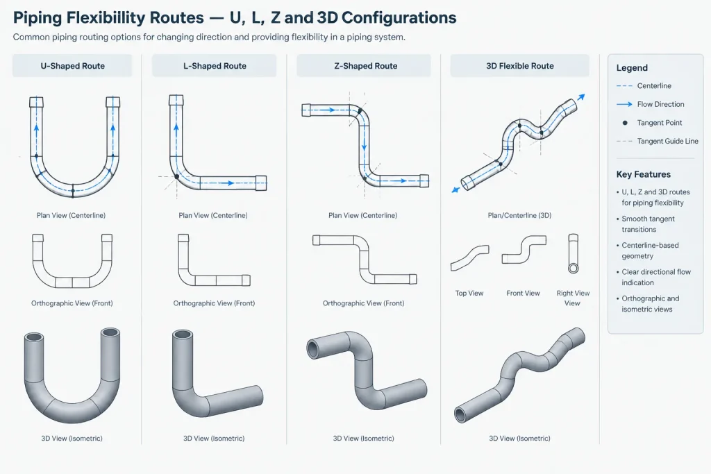
L and Z Configurations
An existing change in direction can provide useful flexibility. An L-shaped route has one major turn, while a Z-shaped route uses two offsetting turns. These arrangements may reduce the need for a separate U-shaped loop, but their suitability cannot be judged from appearance alone.
A routing offset created for obstacle avoidance is not automatically an engineered expansion offset. Its legs may be too short, its supports may prevent the needed displacement, or its movement may be directed toward an unsuitable connection.
Three-Dimensional Loops
Some routes use changes in both elevation and plan direction. These configurations can solve congestion problems, but they are more difficult to interpret on plan drawings and piping isometrics. Coordinates, elevations, elbow orientation, and support references become especially important.
Which Dimensions Should the CAD Model Control?
Expansion-loop geometry is normally established from the pipe centerline. Centerline control keeps the routing relationship understandable when pipe size or wall thickness changes. The physical envelope must still be checked using the applicable outside diameter, fittings, insulation, supports, and nearby objects.
Useful layout controls include:
- The centerline location of the main pipe run.
- The centerline-to-centerline projection of each loop leg.
- The location of the cross leg or return leg.
- Elbow tangent points or another consistent geometric reference.
- Pipe elevations and the plane in which the loop is routed.
- Anchor, guide, line-stop, and support locations.
- Nearby structural, equipment, platform, and maintenance envelopes.
Do not define the same geometry through several competing dimension chains. For example, dimensioning both every straight segment and the total loop envelope can create a closed dimensional loop if fitting takeouts or elbow geometry later changes. Control the functional geometry and derive secondary dimensions where practical.
Anchors, Guides, Stops, and Supports
The response of an expansion loop depends heavily on restraint conditions. A geometrically accurate loop can behave differently from the design intent if a support blocks movement in the wrong direction.
| Item | Primary documentation purpose | CAD review question |
|---|---|---|
| Anchor | Identifies a location intended to restrain specified pipe translations and, where applicable, rotations | Is the restraint function defined, and is the supporting structure coordinated? |
| Guide | Directs pipe movement while permitting movement along an intended axis | Does the guide orientation match the expected displacement? |
| Line stop | Restrains axial movement in one or both directions, depending on its design | Is the blocked direction shown or described clearly? |
| Sliding support | Carries vertical load while allowing selected horizontal movement | Is there enough travel surface and clearance for movement? |
| Spring support | Supports a pipe that undergoes significant vertical movement | Are the support location, movement case, and specialist data coordinated? |
These labels should not be treated as interchangeable. A pipe shoe resting on steel does not automatically represent a frictionless sliding point, and a generic support symbol does not fully define restraint behavior. The stress or flexibility model needs support assumptions that correspond to the intended physical detail.
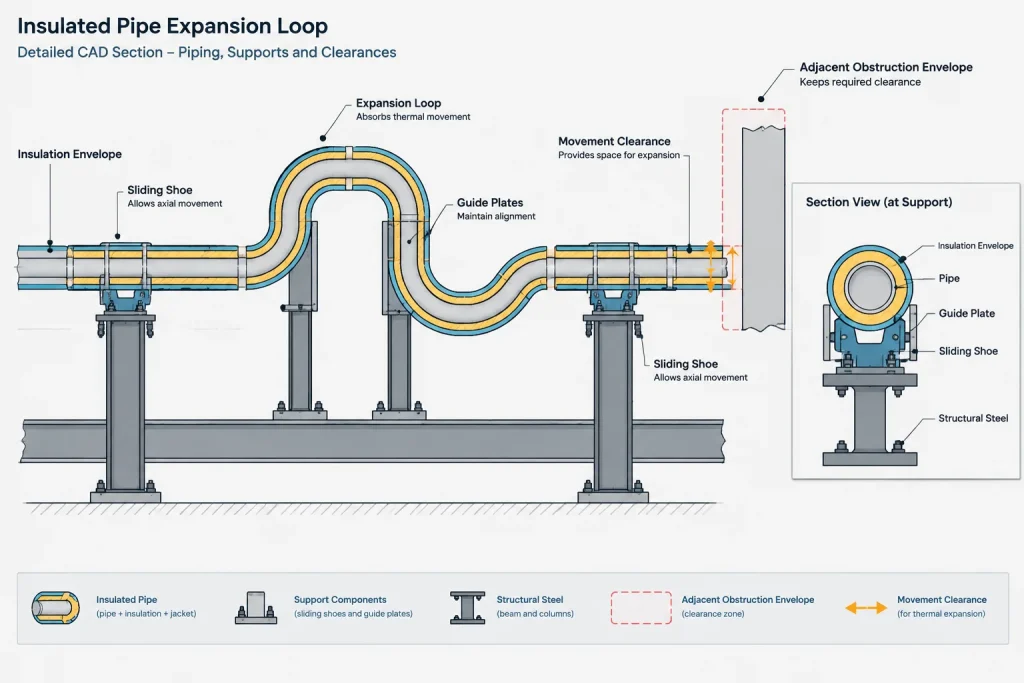
Similarly, an anchor symbol in a piping model does not prove that the surrounding structure can resist the resulting loads. Structural interfaces, attachment details, and load-transfer responsibilities require separate coordination.
Cold Geometry and Operating Movement
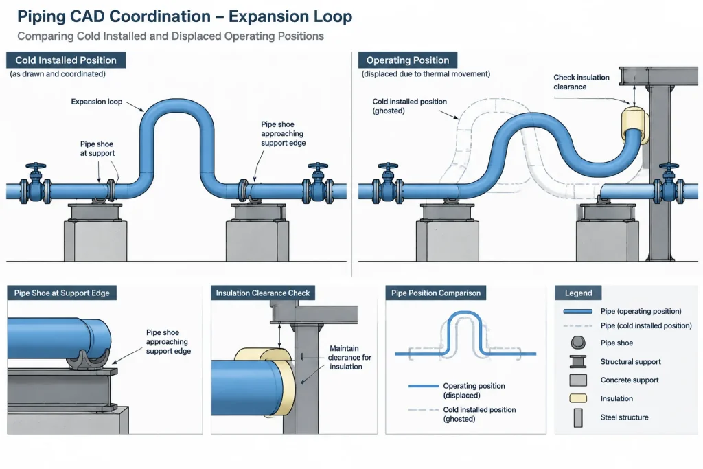
Piping is commonly modeled in an installed or reference condition. During operation, points along the loop may move away from those modeled coordinates. The designer should distinguish between the modeled geometry and any displayed operating-position overlay.
Movement information may include directional arrows, displacement envelopes, alternate-position graphics, or tabulated point movements. Whatever method is used, the drawing should identify the applicable operating case and avoid presenting predicted movement as fabrication geometry.
Movement checks should consider more than contact between bare pipe centerlines. Potential conflicts include:
- Insulation contacting steel, walls, or adjacent lines.
- Pipe shoes approaching the edge of support steel.
- Guides running out of usable travel.
- Drain or vent branches moving into nearby objects.
- Valve operators entering platforms or handrails.
- Small-bore connections being forced against local supports.
- Vertical movement reducing required drainage or clearance.
Expansion-Loop CAD Workflow
1. Establish the Design Basis
Confirm the line identification, nominal size, piping specification, insulation status, operating cases, connected equipment, and applicable project requirements. The CAD designer does not need to reproduce the calculation, but the model must use the same routing and component basis as the engineering review.
2. Create Controlled Centerline Geometry
Lay out the loop using consistent centerline references. Use actual fitting geometry from verified project data where dimensions affect tie-ins, support locations, or fabrication. Avoid creating another size by scaling a component symbol or solid.
3. Add the Physical Envelope
Check the pipe outside diameter, fitting bodies, flange or valve projections, insulation, shoes, clamps, and removable covers. A centerline route that clears an obstruction may still fail once the full envelope is represented.
4. Place Supports by Function
Identify where the pipe is supported and what each support is intended to restrain. Coordinate guide axes and stop directions with the expected movement. If the support type is not yet finalized, mark the item as preliminary rather than assigning unsupported behavior.
5. Coordinate the Flexibility-Analysis Handoff
Provide a model or extract that preserves node locations, fitting geometry, terminal points, support functions, and equipment interfaces. Record assumptions that are not obvious from geometry, including imposed displacements or modeled restraint directions.
6. Reconcile Returned Results
Engineering review may change leg lengths, support locations, guide directions, or nearby routing. Update the CAD model and related drawings together. Do not leave the model showing one arrangement while the analysis and support documents refer to another.
7. Review Fabrication and Field Access
Confirm that the loop can be fabricated, transported, erected, welded, inspected, insulated, and supported. Large loop-shaped spools may require practical spool breaks or field welds even when a continuous assembly is easy to represent digitally.
Common Modeling Mistakes
- Treating any offset as an expansion loop: A routing detour has no verified flexibility function until it is evaluated with its actual restraints and design conditions.
- Checking only the cold position: Operating movement may create clashes that are absent in the base model.
- Using approximate elbow geometry: Incorrect takeouts alter tangent locations, straight lengths, and the overall loop envelope.
- Adding supports without restraint logic: A guide or stop placed for convenience can change the load path and reduce intended flexibility.
- Ignoring insulation and shoes: These items often govern clearances around structural steel and adjacent piping.
- Moving analyzed points without review: A small routing revision can change leg flexibility, support spacing, or terminal loads.
- Assuming symmetry: A visually symmetrical loop may have nonsymmetrical movement because of different restraints, branch loads, or connected systems.
What the Final Documentation Should Communicate
A coordinated expansion-loop package should make the route, dimensions, elevations, fitting types, support functions, and interface points understandable across the 3D model, general arrangement drawings, isometrics, support details, and flexibility model. Important movement or restraint assumptions should not exist only in an informal markup.
The CAD model provides the controlled geometric basis, but it is not a substitute for engineering evaluation. A useful model shows what is installed, where it is supported, what space is reserved for movement, and which features remain subject to specialist verification. That separation between accurate geometry and verified performance is essential when documenting piping expansion loops in CAD.
Using the CAD Model as a Coordination Record
An expansion-loop model is most useful when another reviewer can identify the controlled route, understand the restraint intent, and distinguish installed geometry from predicted movement. Symbols and component names alone may not provide that clarity. Guide axes, stop directions, support functions, reference coordinates, movement cases, and preliminary items should be communicated consistently across the project documents.
The model should also preserve the relationship between analyzed points and physical components. If an elbow, support, terminal connection, or loop leg moves during layout development, the associated flexibility assumptions may no longer describe the current route. Revision control should therefore include both geometric changes and changes to restraint behavior.
A Practical Coordination Test
Before treating an expansion-loop layout as coordinated, reviewers should be able to answer the following questions from the model and supporting documents:
- Which centerline references control the loop geometry?
- Which locations are intended to anchor, guide, stop, or vertically support the pipe?
- Which movement directions are permitted and which are restrained?
- Does the represented envelope include fittings, insulation, shoes, operators, and other projecting items?
- Are operating-position graphics clearly separated from fabrication geometry?
- Have equipment interfaces and structural attachment responsibilities been identified?
- Do the CAD model, flexibility model, isometrics, and support documents describe the same arrangement?
If these questions cannot be answered consistently, the route may be graphically complete but not yet ready to serve as a reliable engineering coordination basis.
Managing Changes After Flexibility Review
Returned engineering comments should be incorporated as controlled design changes rather than isolated model edits. A revised support location can affect available travel, structural loading, access, and drawing annotations. A routing change can alter fitting tangent points, straight pipe lengths, movement clearances, and equipment interface loads.
Where the final restraint detail remains unresolved, the documentation should state that status instead of assigning a definitive support function. Clear status identification helps prevent preliminary assumptions from being interpreted as approved construction information.
Frequently Asked Questions
Does a U-shaped pipe route automatically qualify as an expansion loop?
No. The shape may provide flexibility, but its engineering function depends on the actual geometry, pipe properties, operating conditions, connected systems, and restraints. It must be evaluated using the project design basis.
Should expansion-loop dimensions be based on pipe centerlines?
Centerlines are generally the clearest basis for controlling routing geometry. The complete physical envelope must still account for pipe outside diameter, fittings, insulation, supports, valves, and nearby objects.
Why must guide orientation be shown?
A guide is intended to direct movement rather than block every direction. Showing its orientation helps the CAD layout, support detail, and flexibility model represent the same restraint behavior.
Can operating movement be modeled as the installed pipe position?
The installed or reference geometry should remain distinguishable from a predicted operating position. Movement overlays, arrows, or envelopes should identify the applicable case and should not be mistaken for fabrication coordinates.
Is a pipe shoe the same as a sliding support?
Not necessarily. A shoe is a physical pipe attachment, while sliding behavior depends on the complete support arrangement, contact surfaces, restraints, and project assumptions. The intended function should be defined explicitly.
When should an expansion-loop CAD model be reviewed again?
Review is appropriate whenever routing, fitting geometry, support locations, restraint directions, terminal conditions, connected equipment, or nearby clearance envelopes change. These revisions can affect both movement and load paths.