
Piping expansion loops in CAD require more than accurate linework. The model must show how the flexible route relates to anchors, guides, supports, equipment connections, access areas, and the surrounding structure. A well-organized drawing helps reviewers understand the approved flexibility concept without suggesting that the CAD arrangement replaces engineering analysis.
This page is especially useful for piping designers, CAD drafters, and coordinators preparing plan, elevation, isometric, or plant-model views. Use the project specification, controlled component library, support documents, and approved flexibility information as the governing sources for geometry and detailing.
Piping expansion loops absorb movement caused by thermal expansion, contraction, equipment displacement, or other forms of controlled flexibility. In CAD, the loop is more than a curved piece of pipe: it is a coordinated arrangement of straight runs, bends, supports, guides, and clearances that must remain understandable and constructible.
This guide explains how to lay out and detail piping expansion loops in CAD without treating the drawing as a substitute for a flexibility analysis. The reference dimensions for pipe, elbows, fittings, and supports should come from the project specification and the applicable engineering calculations. Your CAD model should communicate the approved arrangement clearly and consistently.
What an expansion loop does
When a piping system changes temperature, its connected runs tend to change length. If the route is restrained at equipment or fixed supports, that movement must be accommodated somewhere. An expansion loop provides additional pipe length and directional flexibility so the system can move in a controlled way.
A loop commonly includes parallel straight legs connected by elbows. Depending on the design, the loop may lie in a horizontal plane, rise vertically, or combine horizontal and vertical changes. The exact geometry depends on the piping system, temperature range, material, anchor locations, available space, support arrangement, and flexibility analysis.
Do not select loop geometry from appearance alone. A visually generous loop may still conflict with a structure, create an unwanted low point, or transmit excessive loads to connected equipment. Conversely, a compact arrangement may be acceptable when it has been engineered and documented correctly.
Expansion loop versus ordinary routing offset
An ordinary piping offset changes the route to avoid an obstruction, reach a connection, or coordinate with another system. An expansion loop is intentionally introduced to provide flexibility. The two may look similar in a plan or isometric view, but their design purposes are different.
| Feature | Ordinary routing offset | Expansion loop |
|---|---|---|
| Primary purpose | Coordination, access, or connection alignment | Controlled accommodation of piping movement |
| Design basis | Layout and constructability requirements | Flexibility analysis and support or anchor strategy |
| Key CAD checks | Clearance, elevation, connectivity, and dimensions | Movement envelope, support interaction, guides, anchors, and clearance |
| Documentation | Shown as part of the normal route | Should be identifiable in the model and related documents |
This distinction matters during design reviews. If a route change is expected to provide flexibility, identify that intent in the model notes, line list, stress documentation, or other project-controlled information rather than relying on the shape alone.
Plan the loop before drawing the geometry
Confirm the design inputs
Before creating the loop, collect the information that controls its location and orientation:

- Line identification, piping class, nominal size, insulation condition, and operating temperature information.
- Anchor, stop, guide, and support locations from the approved support or flexibility design.
- Equipment connection points and allowable movement information provided by the responsible equipment or piping engineer.
- Structural steel, platforms, access ways, roads, electrical routes, instrument connections, and maintenance zones.
- Required drainability, venting, slope, stress, fabrication, and erection constraints.
These inputs determine whether the loop should be horizontal, vertical, or a three-dimensional arrangement. They also determine which apparent clearances are actually available after insulation, coating, support hardware, and construction tolerances are considered.
Reserve a movement envelope
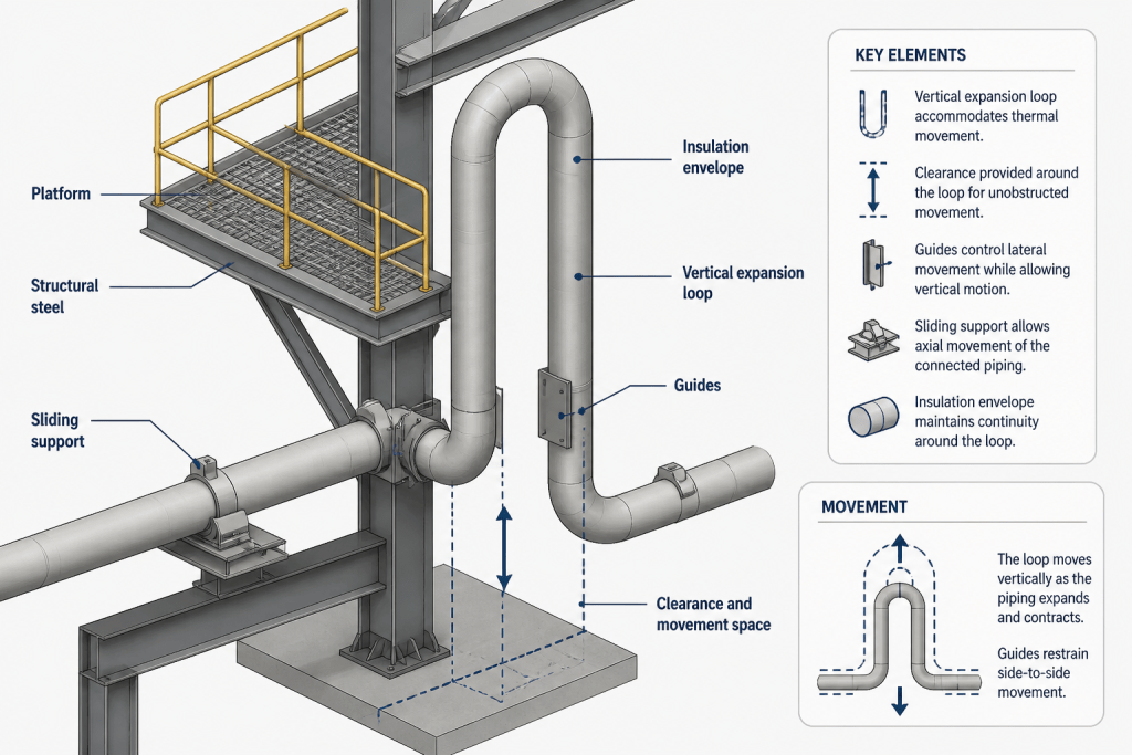
Draw the space required for the pipe in its installed position and the space it may occupy as it moves. The movement envelope is not necessarily a simple rectangle around the line. Elbows rotate or translate as part of the system response, and different points along the loop may move in different directions.
Use a dedicated CAD layer, reference model, or temporary geometry to show the envelope during coordination. Keep it visually distinct from the permanent piping so reviewers can distinguish the physical pipe from the clearance requirement.
Modeling the loop in CAD
Start from known connection points and control points rather than drawing a decorative shape. A reliable sequence is:
- Place the pipe centerline at the approved equipment or line connection coordinates.
- Establish the plane or planes in which the loop will be routed.
- Insert the required bends using the correct elbow representation from the project component library.
- Connect the straight legs with tangent centerline segments.
- Assign elevations and slopes deliberately, especially where the loop changes vertical direction.
- Apply pipe, insulation, and support graphics according to the drawing scale and project CAD standard.
- Compare the resulting model with the approved flexibility arrangement and support concept.
When modeling centerlines, avoid small unintended kinks between elbows and straight runs. These can create misleading lengths, awkward fabrication joints, or disconnected solids. If the project uses a plant design database, verify that each elbow, pipe segment, and support is a recognized catalog or specification item rather than an unclassified graphic.
Coordinate supports, anchors, and guides
A loop does not function independently of its supports. Anchors establish reference points, guides control lateral movement, and directional stops limit movement along selected axes. Sliding supports may allow movement while carrying the pipe, but their actual behavior depends on the engineered support detail and operating conditions.
In CAD, show support intent at a level that lets the reviewer understand how the loop is expected to move. A generic support symbol may be insufficient when the distinction between a guide, line stop, anchor, spring support, or sliding shoe affects the flexibility arrangement.
- Place support symbols at the modeled support locations, not merely at convenient drawing positions.
- Check that a guide or stop does not unintentionally block the movement direction required by the flexibility design.
- Show support steel, shoe orientation, or structural attachments when they control the available movement space.
- Coordinate support elevations with insulation, drainage, platforms, and nearby piping.
- Use notes or identifiers that match the support schedule and project database.
Do not infer support suitability from the two-dimensional appearance of a plan view. Review the elevation and isometric views, and consult the responsible engineering documents where movement or load direction is important.
Detailing horizontal and vertical loops
Horizontal loops
A horizontal loop is often easier to read in plan, but it can consume significant corridor width. Check the outside of each bend, not only the centerline, for structural and maintenance clearance. Also review the location of guides and shoes, because a support may extend beyond the nominal pipe envelope.
Vertical loops
A vertical loop can preserve plan space but may affect access, headroom, drainage, venting, and the elevation of connected branches. Show the key elevations clearly and coordinate the loop with platforms and ladders. A vertical arrangement can also create a high point or low point; confirm that the piping system’s vent and drain requirements remain satisfied.
Three-dimensional loops
Three-dimensional flexibility arrangements are difficult to verify in a single view. Use an isometric or 3D model view, supplemented by plan and elevation views. Mark turning points and support locations so the reviewer can trace the route without guessing which leg is in front or behind another.
Drawing and annotation practices
A clear expansion-loop detail should let another engineer or drafter answer five questions quickly:
- Where does the flexible section begin and end?
- Which supports, guides, stops, and anchors control it?
- What movement or clearance must remain available?
- How does the loop connect to the rest of the line?
- Which dimensions and elevations are controlled by the approved design?
Use centerline dimensions for route definition and outside-envelope information for clearance coordination. Do not mix these dimension types without labeling them. Identify the pipe line number and any relevant support or flexibility reference, and keep annotations associated with the correct view.
Where the loop is intentionally nonstandard, add a concise drafting note directing the reader to the governing project calculation or approved layout. The note should clarify design intent without copying proprietary analysis data into the drawing.
Common CAD mistakes
- Drawing a loop without movement space: The pipe is shown, but its operating movement would collide with steel, insulation, or adjacent lines.
- Using the wrong elbow geometry: The centerline looks plausible while the actual component length or tangent location is incorrect.
- Ignoring support interaction: A support, guide, or stop is placed where it prevents the intended movement.
- Creating an unintentional low point: A three-dimensional route changes drainage behavior without being reviewed.
- Showing only a plan view: Vertical legs, elevations, and crossings cannot be verified.
- Over-dimensioning the loop: Repeated or conflicting dimensions make the drawing difficult to control during revision.
Final review checklist
Before issuing the drawing or model, verify the following:
- The loop geometry matches the approved flexibility arrangement.
- Pipe, elbow, flange, insulation, and support representations match the project specification.
- Plan, elevation, and isometric views agree on connectivity and elevation.
- Movement envelopes are clear of structures, equipment, platforms, and other piping.
- Anchors, guides, stops, and sliding supports are identified and coordinated.
- Drain and vent requirements remain valid after the route change.
- Fabrication joints, access points, and construction sequence are practical.
- Dimensions, elevations, notes, and support references can be traced back to controlled design information.
Well-detailed expansion loops make flexibility intent visible without pretending that CAD alone proves performance. The most reliable workflow combines an engineered movement concept with disciplined centerline modeling, support coordination, clearance checking, and consistent annotation.
How CAD supports expansion-loop engineering
CAD is the communication and coordination layer between the flexibility concept and the construction documents. It can represent the route, identify movement space, expose clashes, and connect the loop to support and equipment information. It does not independently establish whether the arrangement has acceptable stresses, loads, reactions, or equipment movements.
Connect the loop to the wider piping model
Review the loop as part of the complete line rather than as an isolated detail. Changes in nearby branches, valves, drains, vents, insulation, platforms, and structural attachments can affect the available movement space or the practicality of installation. A useful model lets the reviewer trace the line from its connection points through the flexible section and onward to its restraints.
- Use consistent line identification and support references across drawings and the plant model.
- Keep temporary movement-envelope geometry separate from permanent pipe and support graphics.
- Use plan, elevation, and isometric views together when the route changes plane.
- Check both centerline connectivity and the physical envelope of pipe, fittings, insulation, shoes, and support hardware.
Separate design intent from drafting convenience
Efficient CAD workflows often use reusable blocks, parametric components, catalog items, or routing tools. These tools improve consistency only when their elbow geometry, connection points, support representations, and specification assignments match the project requirements. A visually clean loop can still be incorrect if it uses an unapproved component, omits a restraint, or places a support for convenience rather than at the engineered location.
When revisions affect loop orientation, support placement, connection elevation, or nearby clearance, route the change through the project review process. Preserve traceability to the controlled flexibility arrangement instead of allowing an apparently minor drafting change to become an undocumented design change.
Relationship to related piping layouts
Expansion-loop detailing overlaps with pipe-rack routing, offsets, valve access, crossings, and support design, but its governing purpose is controlled flexibility. A routing offset may solve a coordination problem without contributing meaningful flexibility, while a loop must be reviewed for movement, restraint interaction, and clearance throughout operation. Treating these purposes separately makes design reviews more precise and reduces the risk of assuming that any bend in the route is a flexibility feature.
Frequently asked questions
Is a piping expansion loop the same as a routing offset?
No. A routing offset primarily coordinates the pipe with an obstruction, connection, or access requirement. An expansion loop is intentionally arranged to accommodate controlled piping movement and is governed by the flexibility concept, restraint strategy, and related engineering review.
Can CAD determine the required expansion-loop geometry?
CAD can represent and check an approved arrangement, but it should not be used as the sole method for determining loop geometry. The responsible piping or stress engineer must establish the design basis, movement expectations, restraint concept, and applicable acceptance criteria.
Why should movement envelopes be shown in the model?
A movement envelope makes the space required by the operating pipe visible during coordination. It helps reviewers identify conflicts with steel, equipment, insulation, access routes, supports, and adjacent piping that may not be apparent from the installed centerline alone.
What views are needed for a three-dimensional expansion loop?
Use coordinated plan, elevation, and isometric or three-dimensional views. The views should agree on connectivity, elevations, turning points, supports, and the surrounding clearance. A single plan view may hide vertical legs, crossings, or unintended high and low points.
How should supports and guides be shown?
Show them at their modeled locations and identify their intended function when that function affects movement. Distinguish anchors, guides, stops, sliding supports, spring supports, and other restraint types when a generic symbol would obscure the flexibility arrangement.
What should be checked before issuing the CAD detail?
Confirm that the route matches the approved flexibility arrangement, the component and support representations match project requirements, movement space remains available, the views agree, drainage and venting are preserved, and dimensions and notes can be traced to controlled design information.